It’s been a while sice we last updated our website, and although we regularly post pictures and updates on our Instagram, Flickr and Facebook pages, we are probably overdue for an update here.
PMV S1153S
The overhaul, partial re-plank and repaint of our PMV have pretty much been completed now apart from the odd ‘finishing off’ punch list items, which will be attended to as and when.
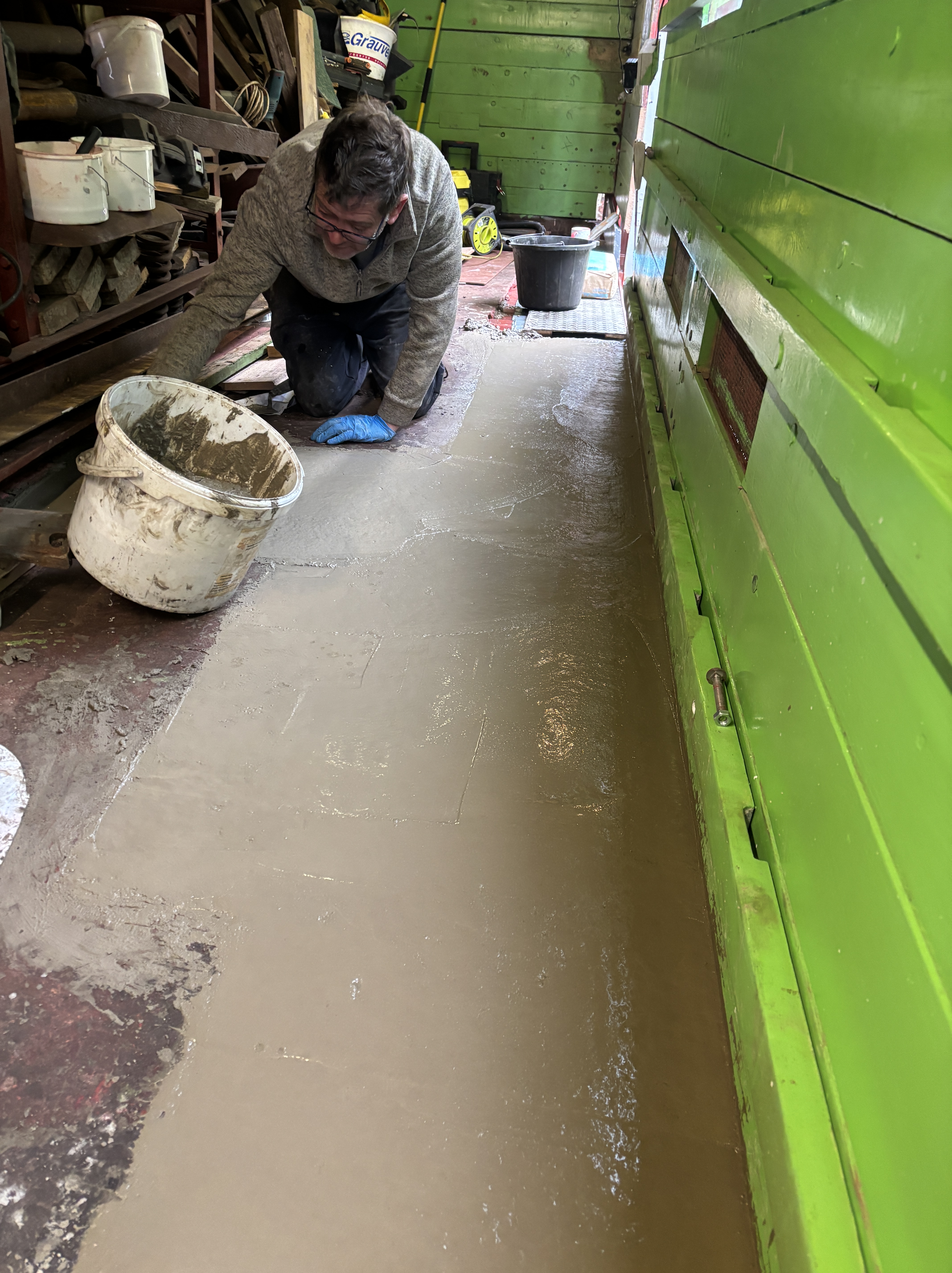
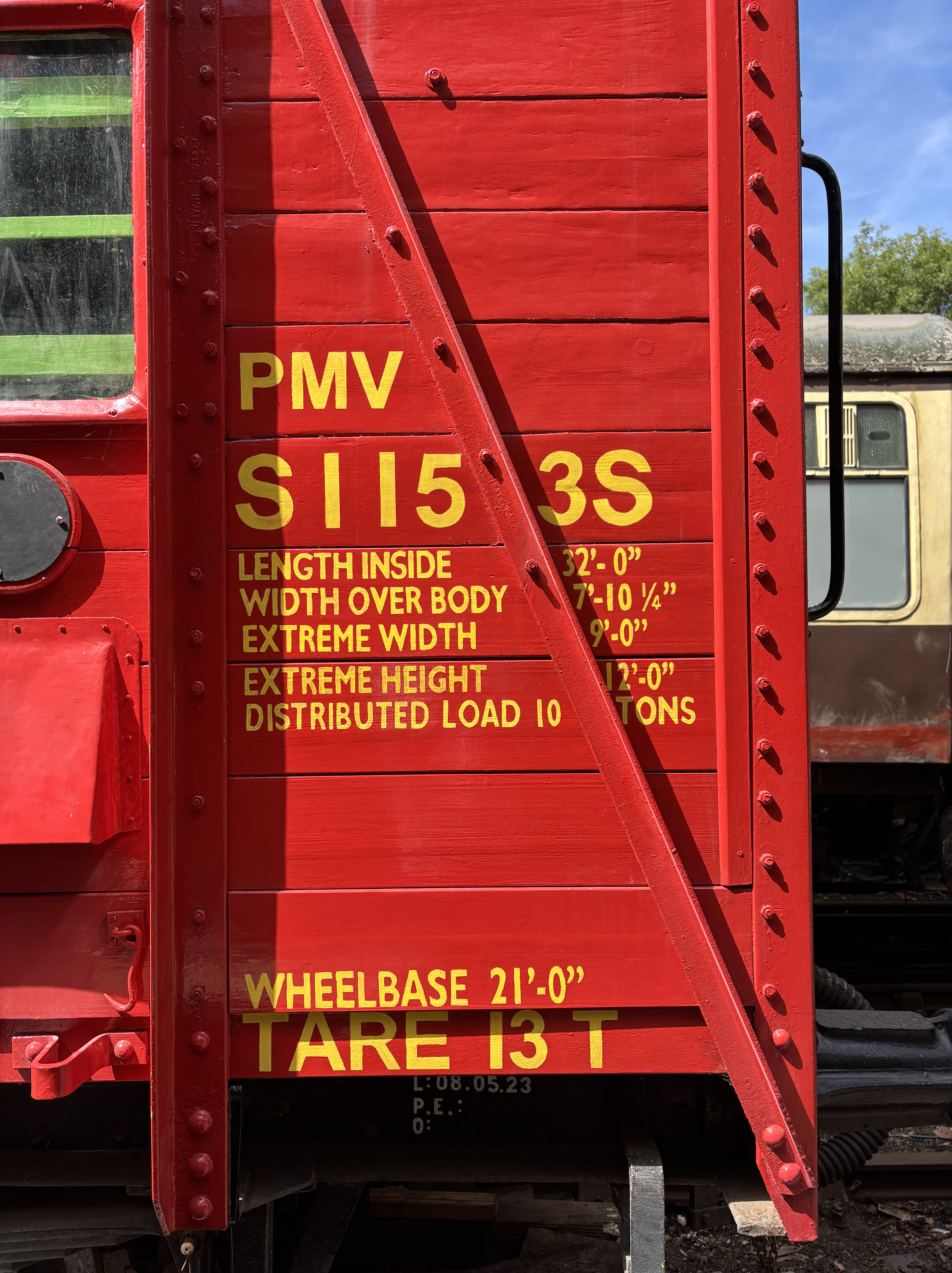
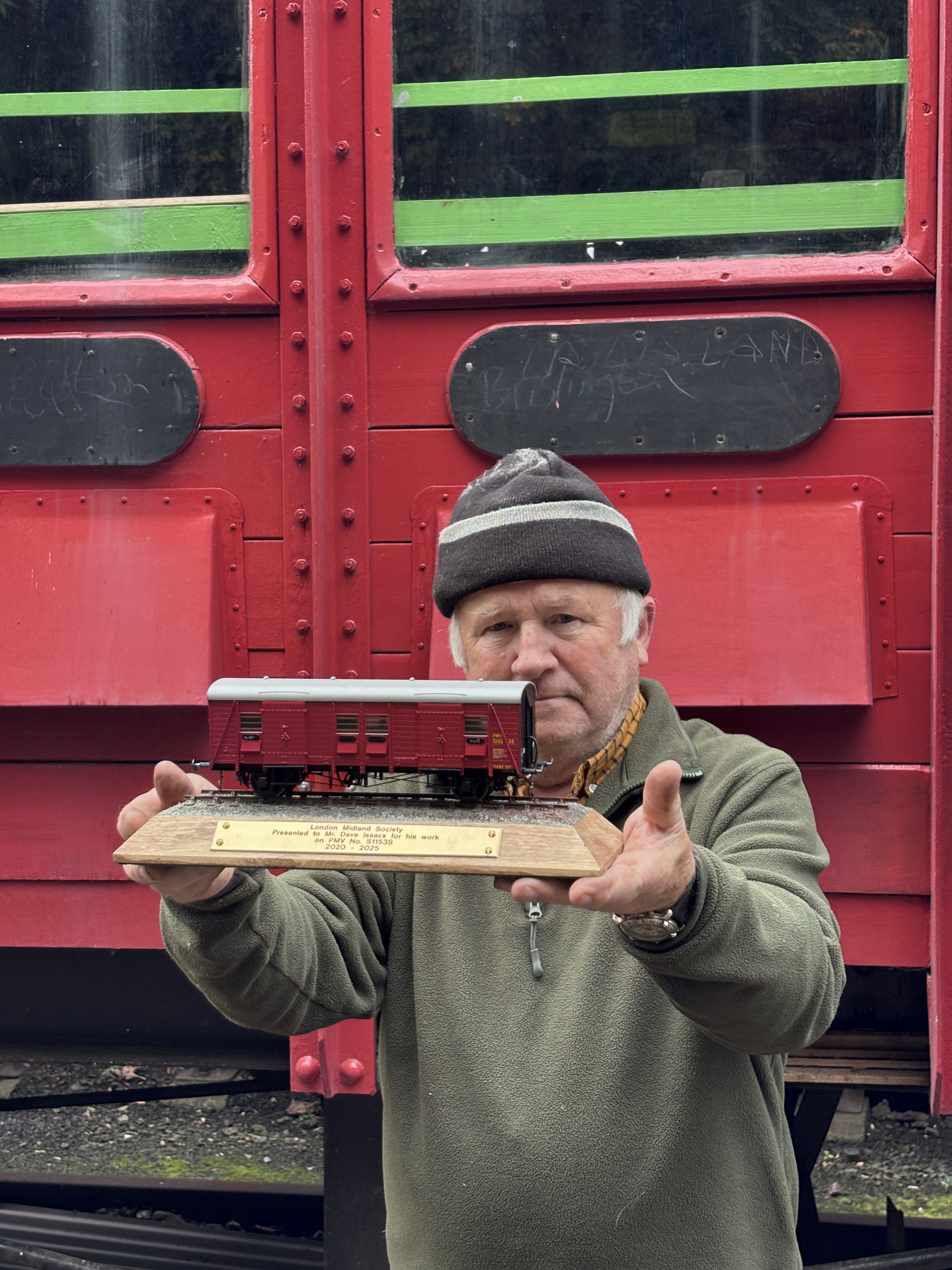
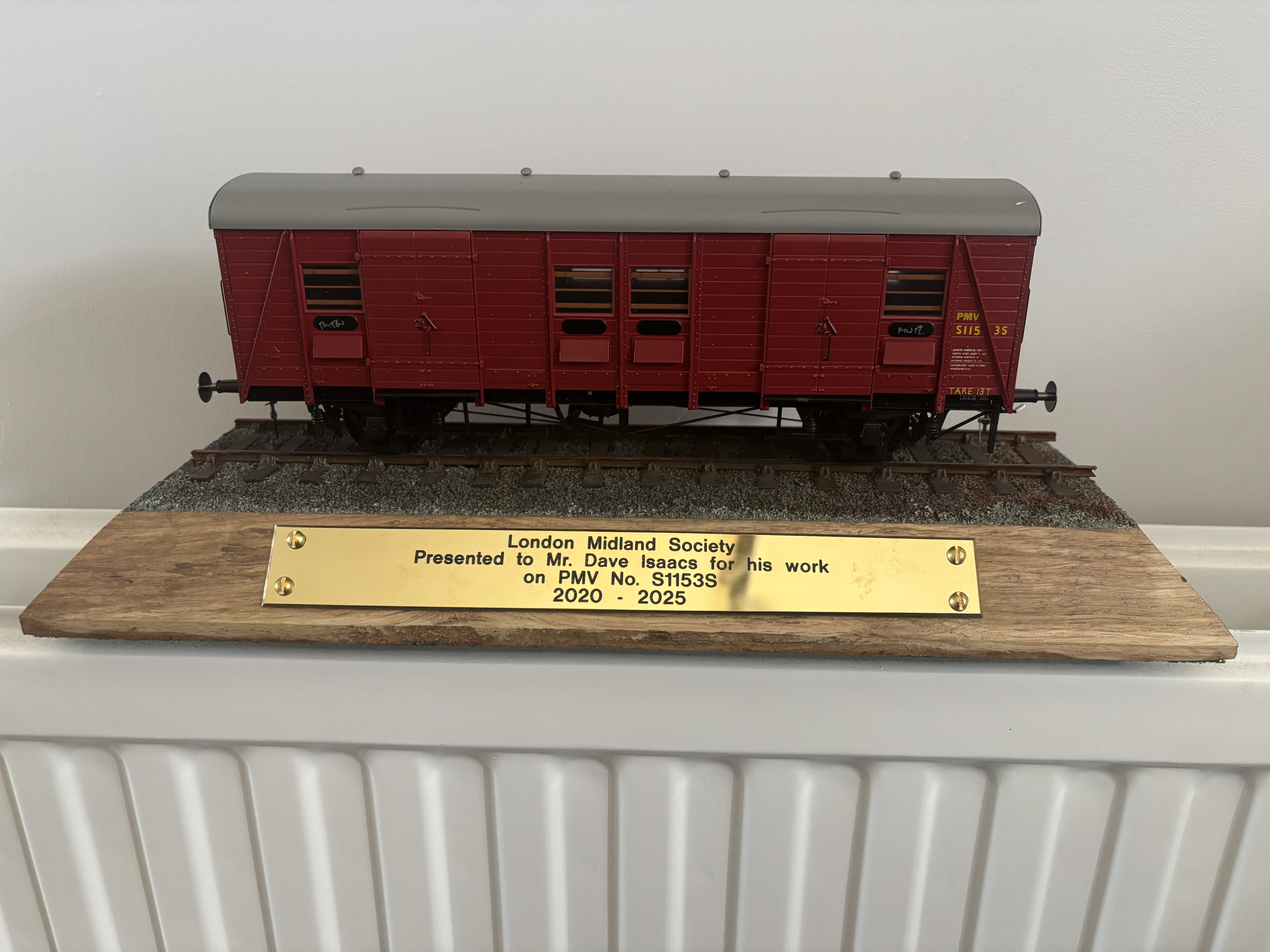
Finalising the repair of the floor on the Eastern side of the PMV. Newly sign-written lettering on the North-Eastern corner following some further plank replacementOur mid-week gang stalwart Dave has put in 1000s of hours on the PMV since 2020. As a vote of thanks for his tireless effort, he was presented with this O gauge model (Heljan) on a commemorative stand.Dave’s commemomrative model prior to handover.
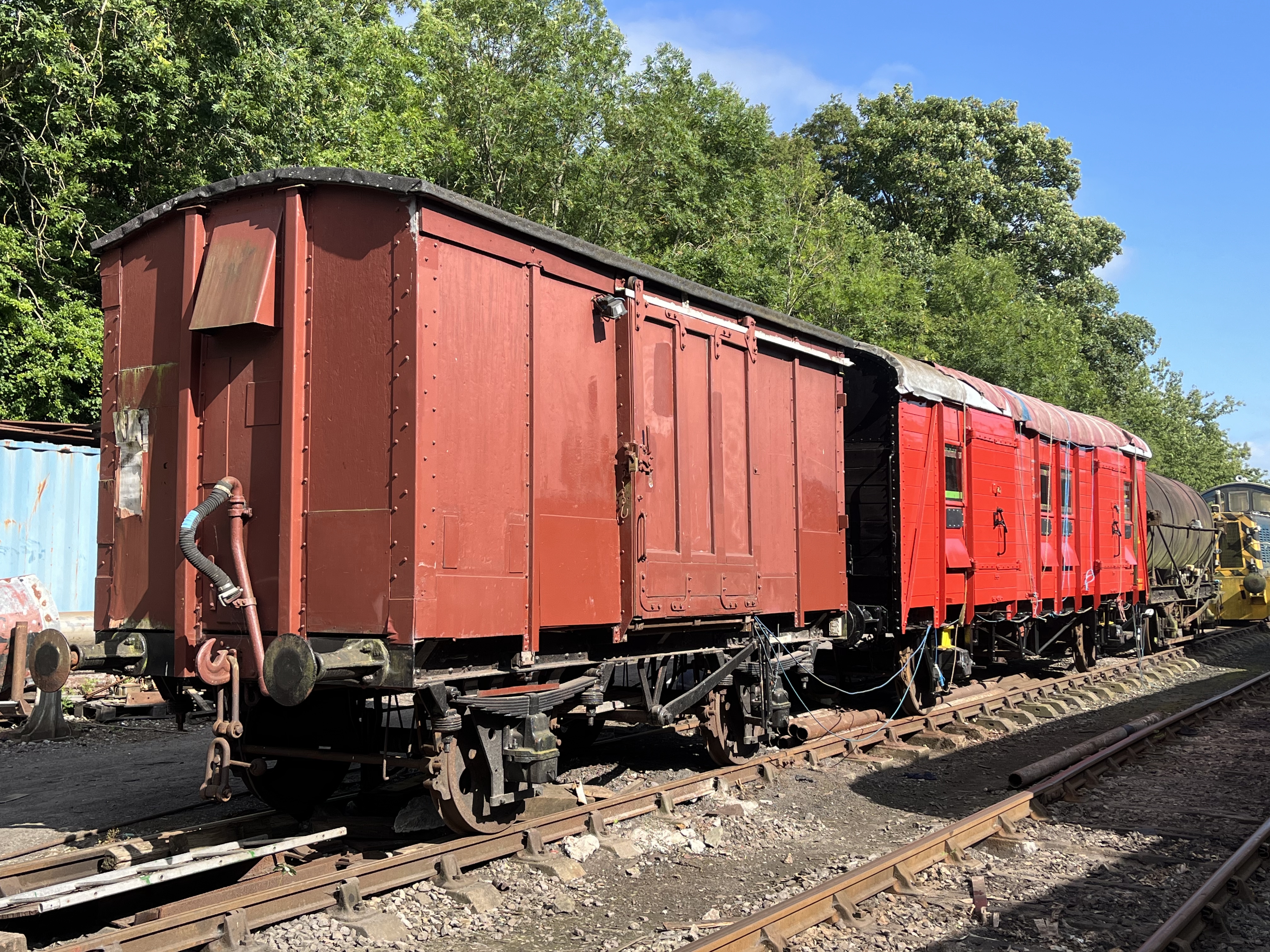
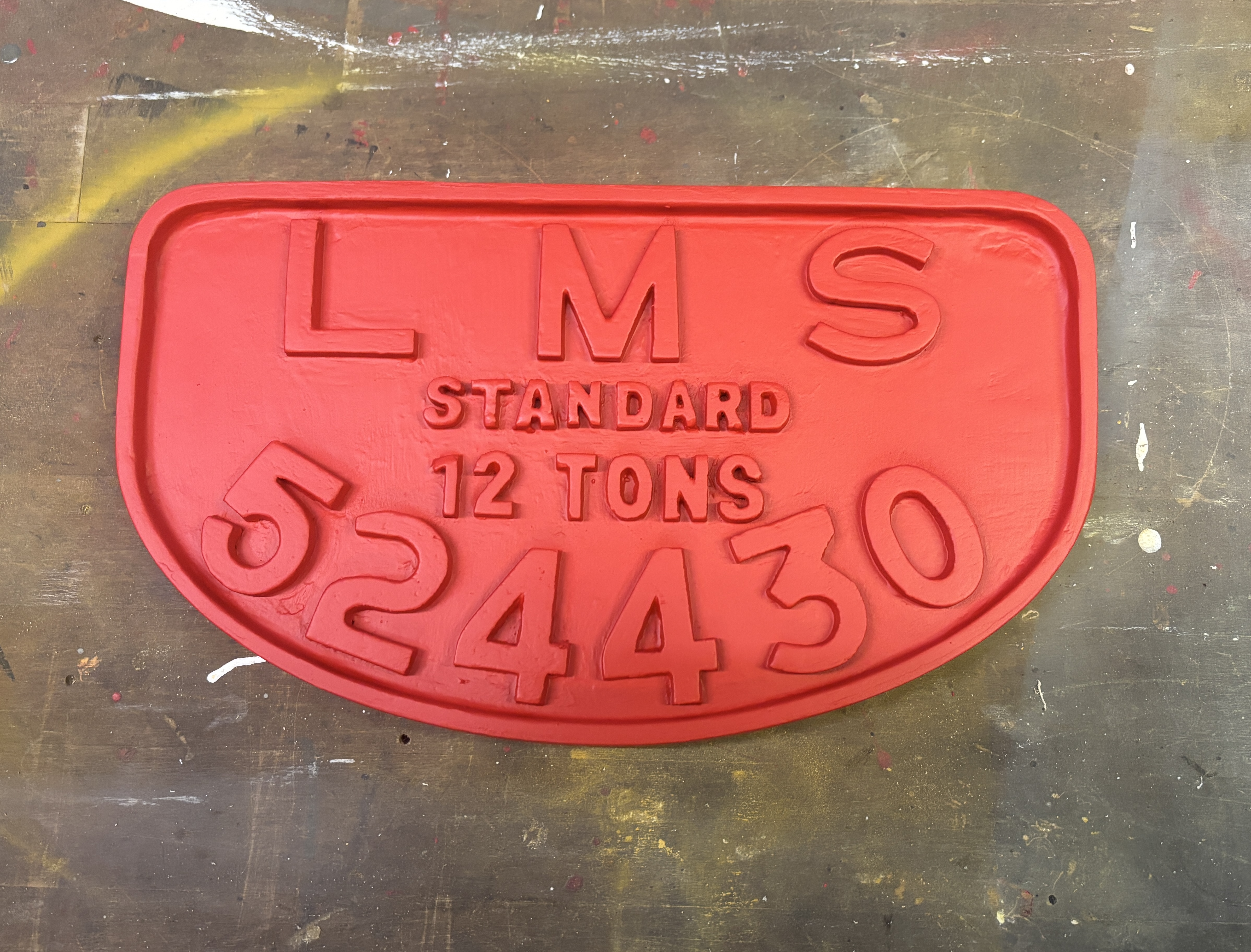
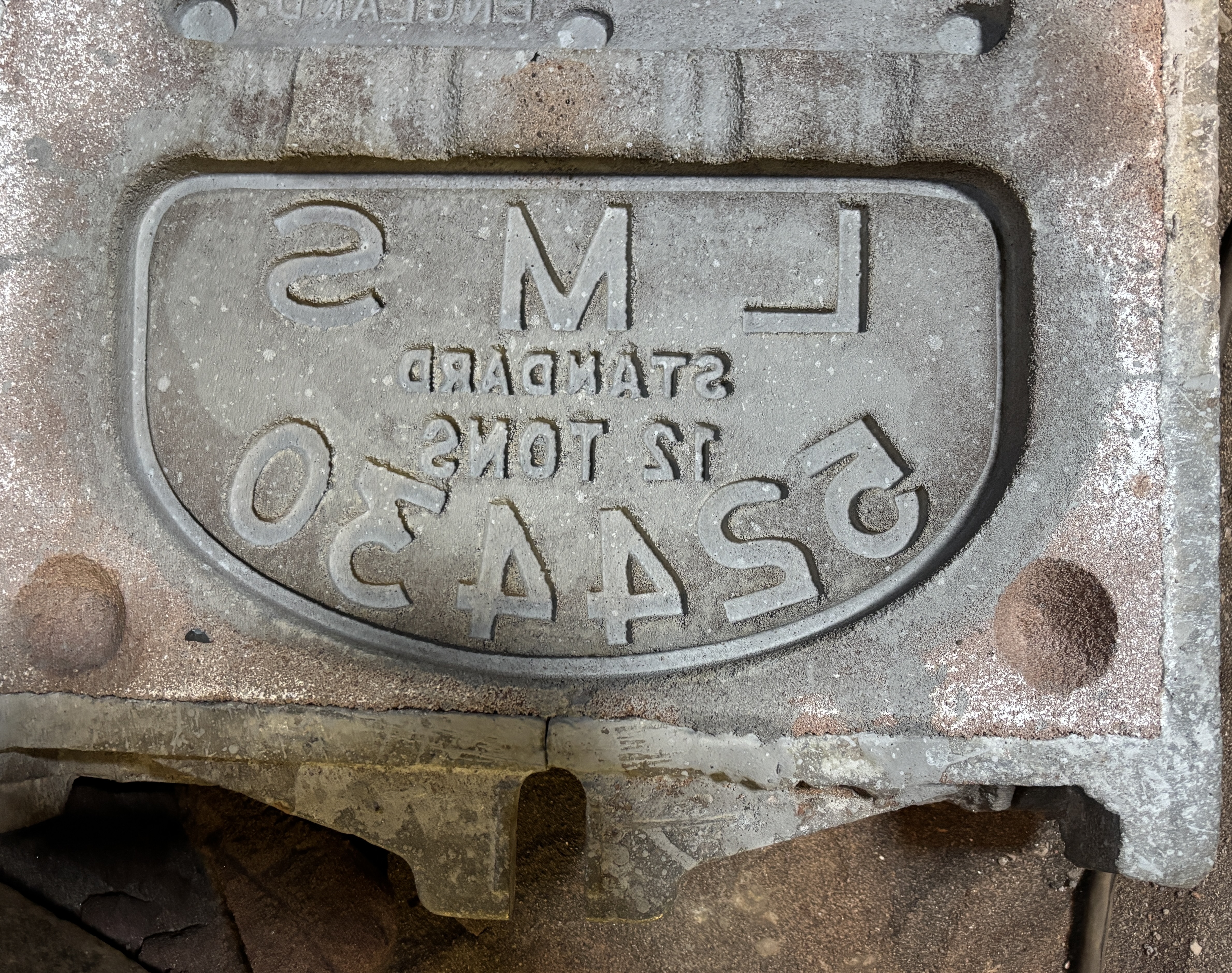
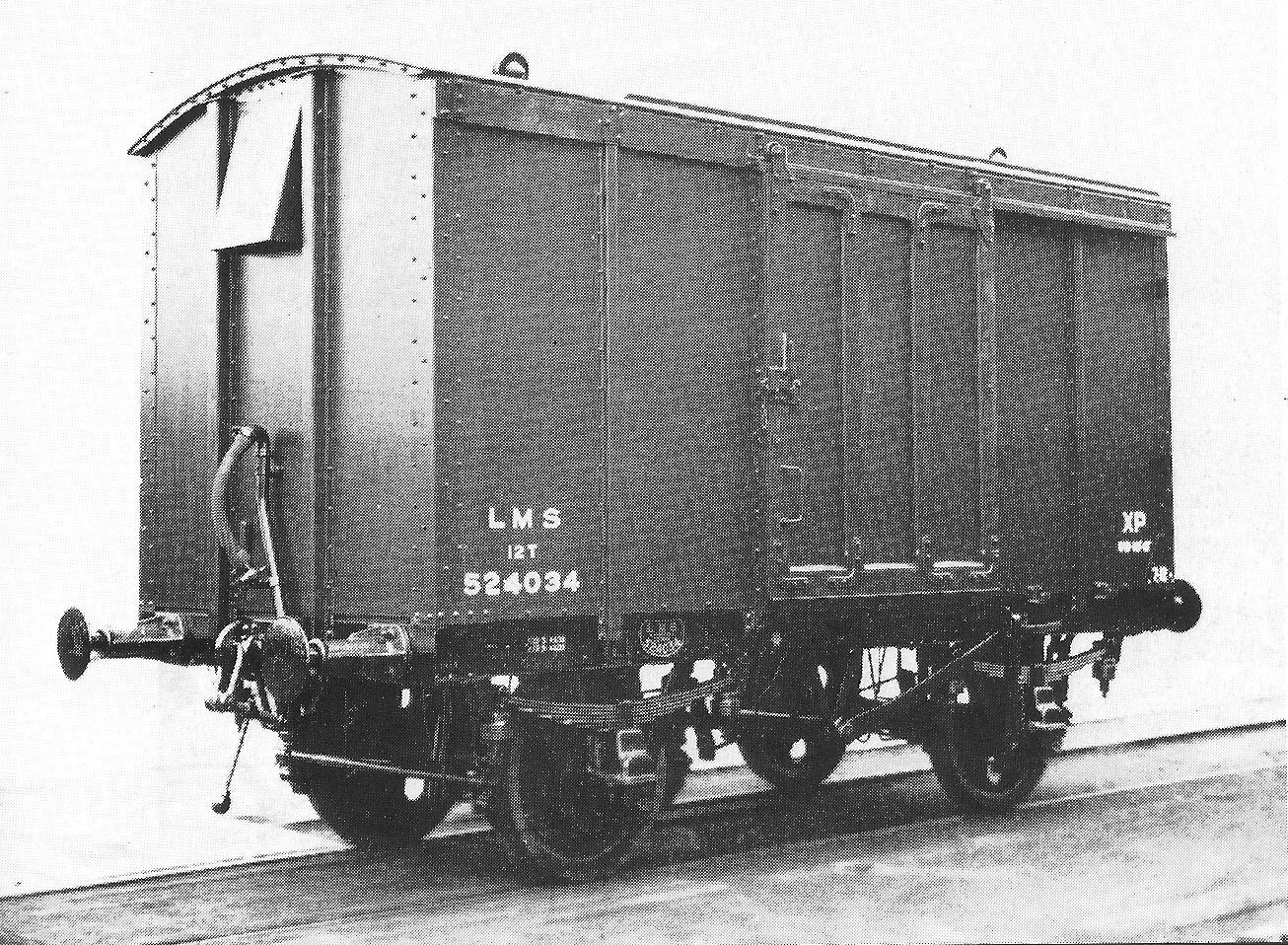
LMS 12Ton Box Van No. 524430
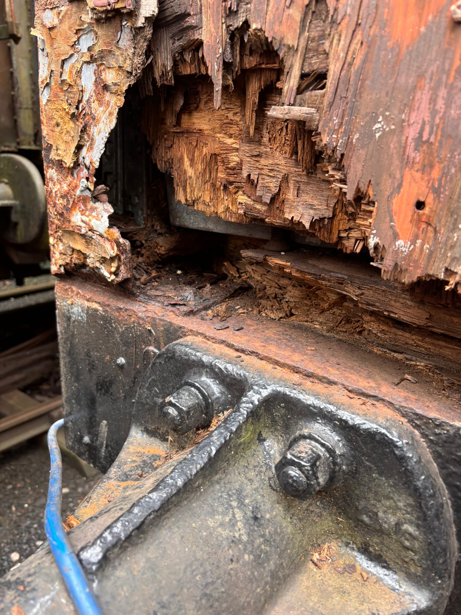
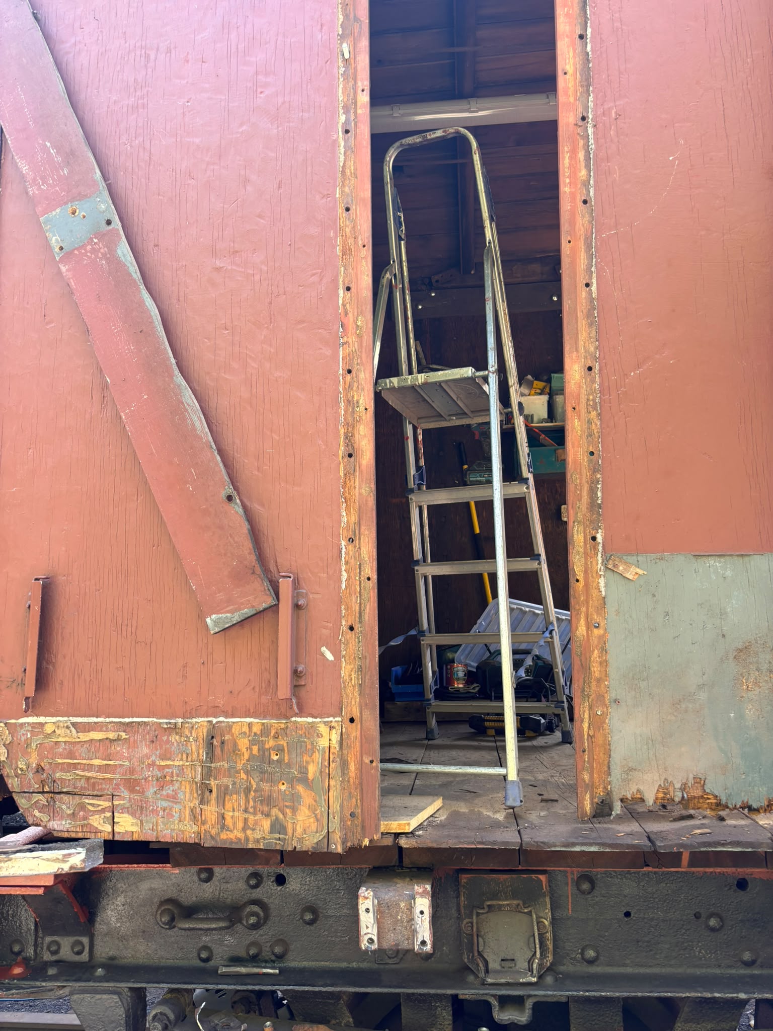
This is the ‘other’ vehicle in our small fleet, and serves as a heavy store van for loco parts and tooling, etc. Whilst it has had various attention over the years, and at first glance appears in reasonable condition, it is actually in dire need of some serious TLC. Leaving aside the ocassional visit to railway works and covered goods sheds and stations whilst it was in service, this van has essentially been ‘outside’ for the majority of its life (81 years old at time of writing). We have therefore bitten the bullet and commenced a rolling overhaul to fix the rot and replace the sides with new plywood, as well as in the fullness of time re-covering the roof and undertaking a cosmetic overhaul of the chassis.
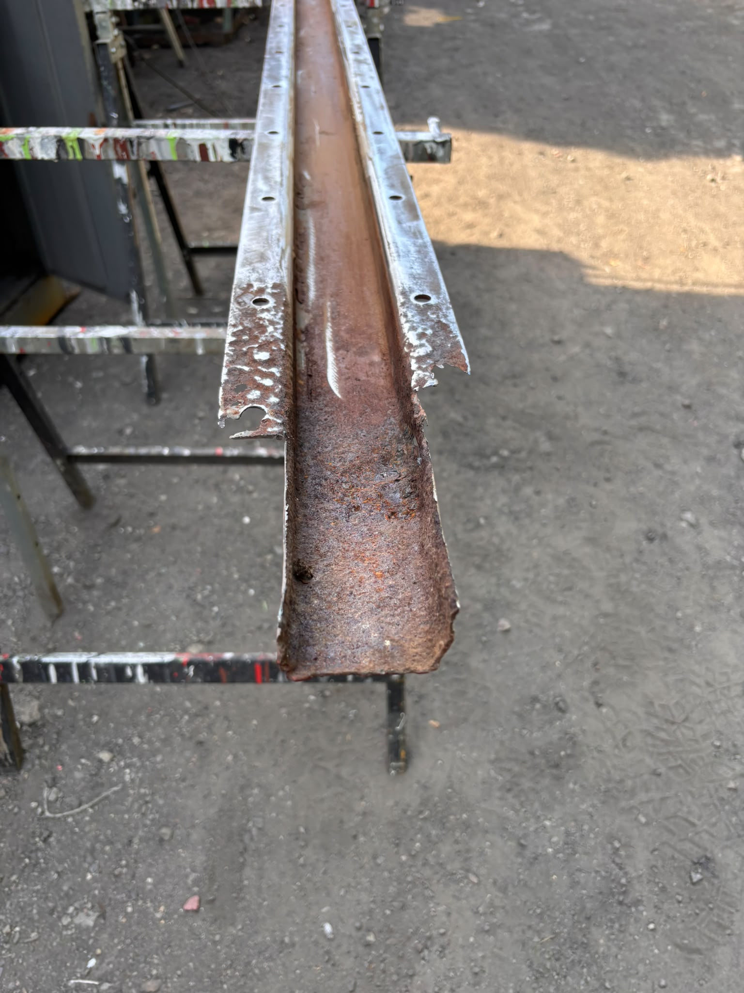
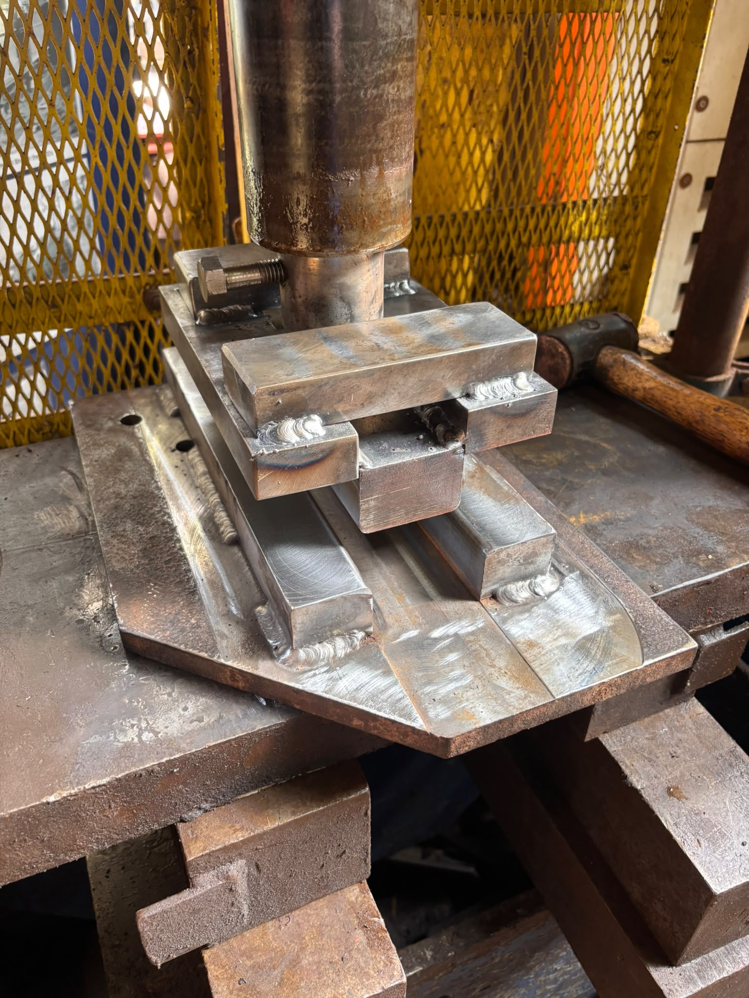
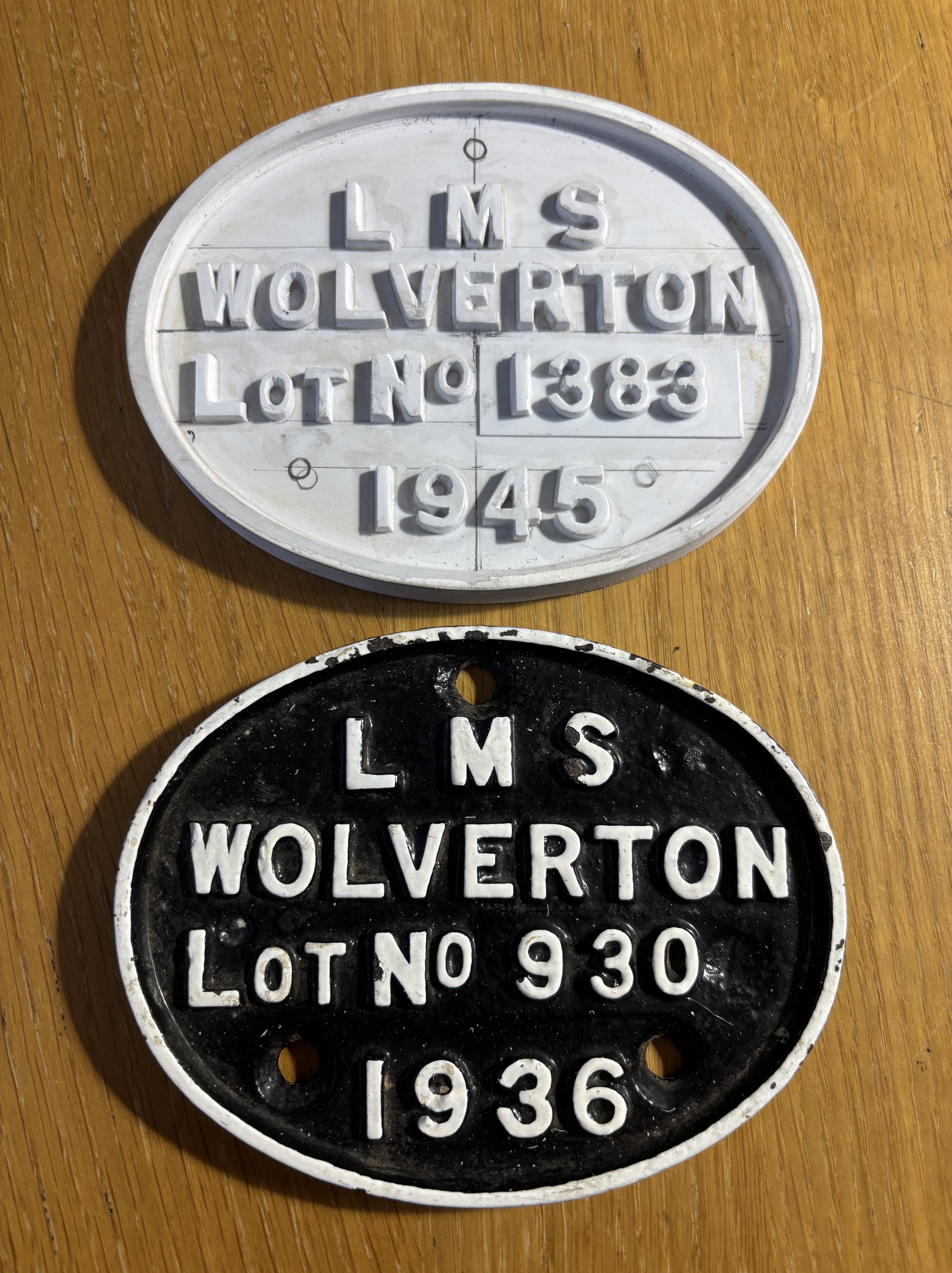
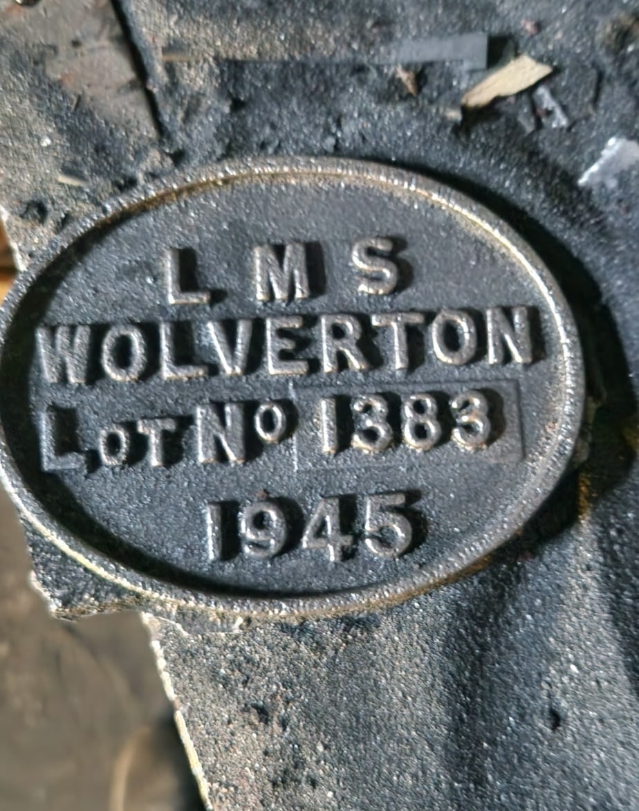
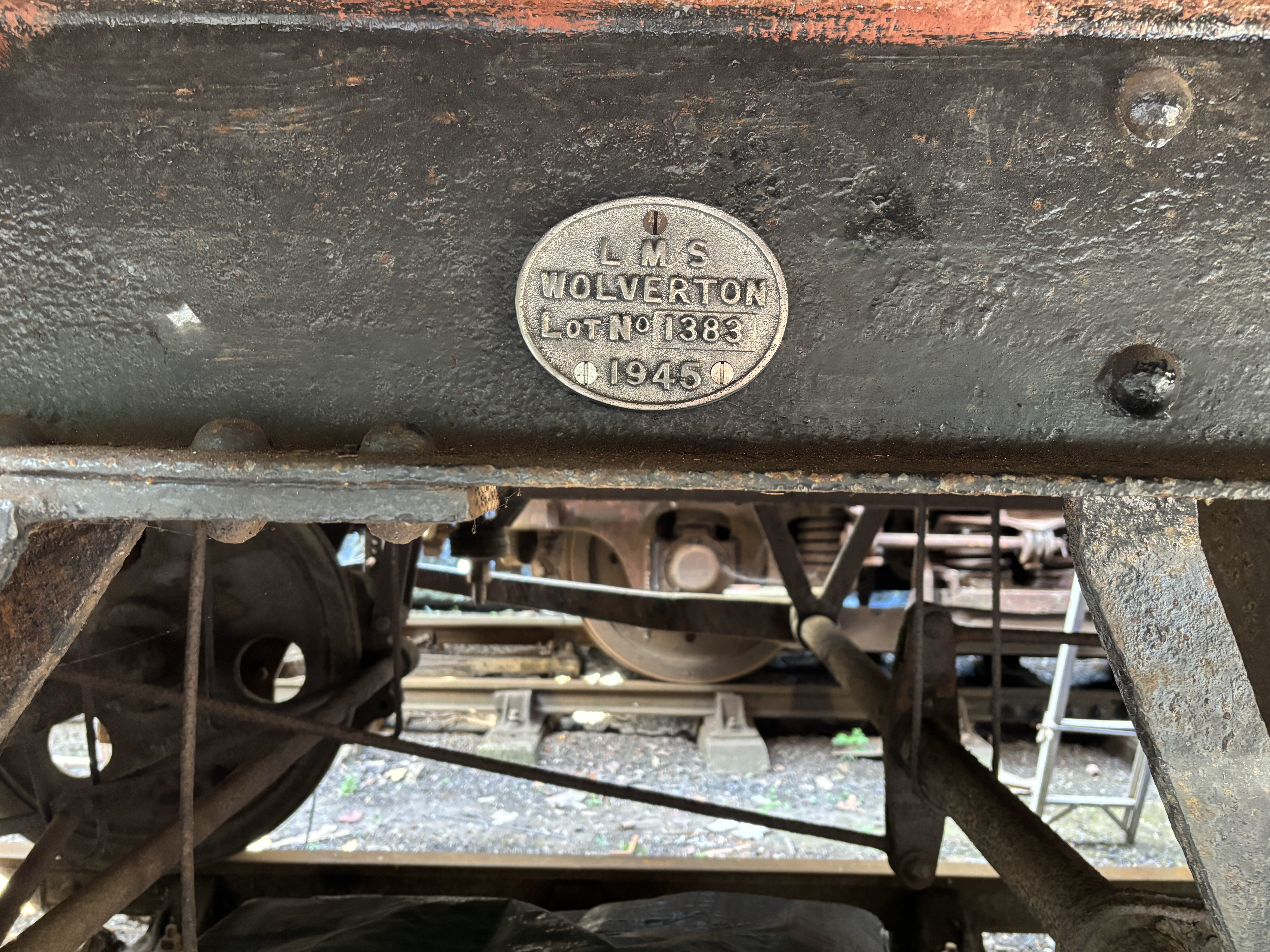
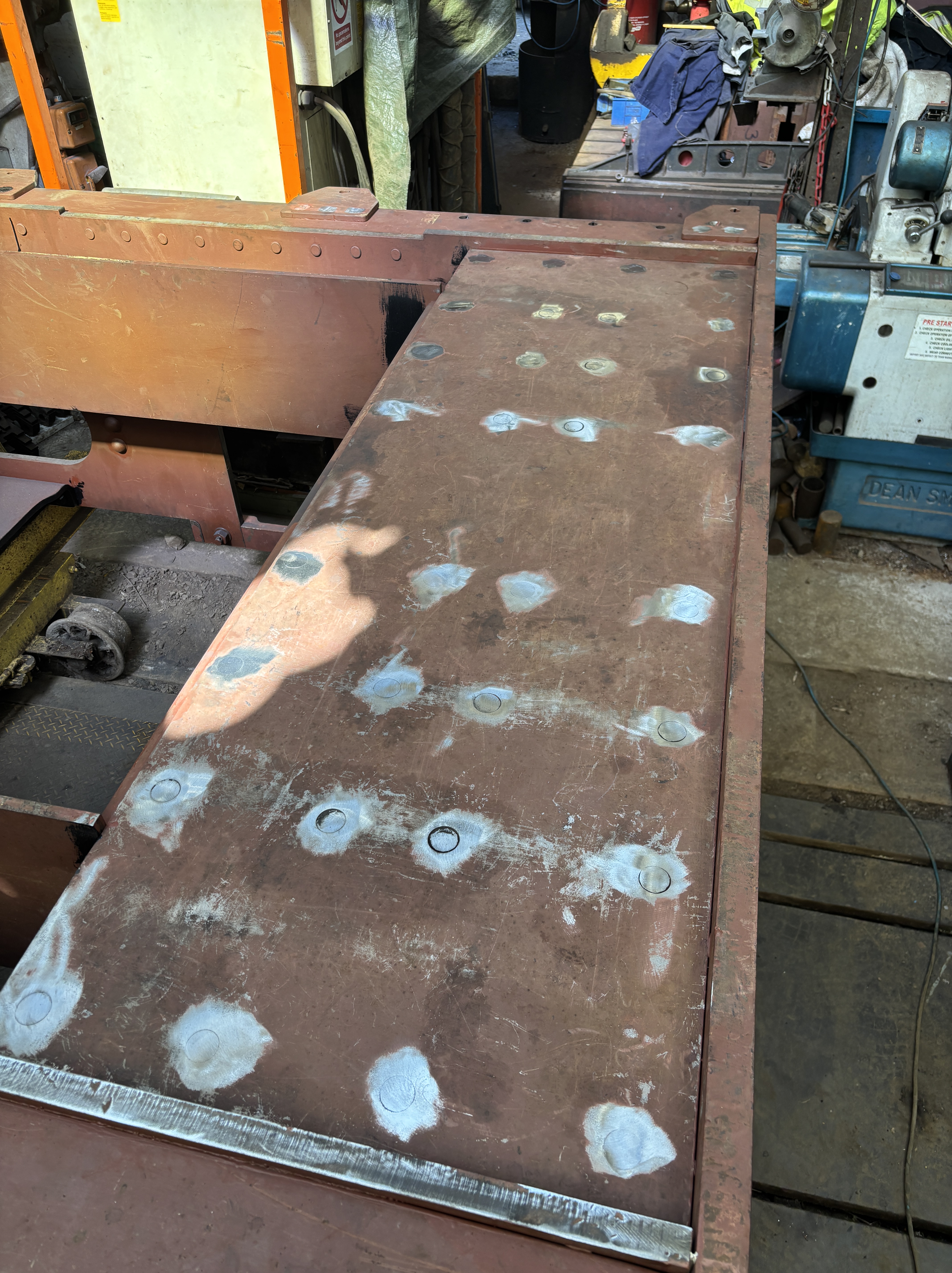
A view of one corner of the van above the bufferstock showing how bad the deterioration is. Rotten floor board and disintegrating plywood sides… and it’s like this pretty much all over.A view of the side of the van showing the remains of the plywood side boards and evidence of earlier ‘botch’ repairs carried out some time ago. One of the mid-side vertical support channels which provide rigidity to the van and give the plywood side something to bolt to. As you can see, this has rotted away to nothing on the lower 8″ or so.Bottom section of the side panel support ‘U’ piece showing what’s left – or rather what isn’t left – of the lower section.Because trying to weld repair this U piece turned out to be almost impossible, we are going to make some new sections to allow a better and stronger repair to be made. This press tool has been knocked up from bits of old steel scrap and off-cuts to allow us to press out some new sections. Seen here in our 100T hydraulic press, which unfortunately decided to break down just as we were pressing the first piece…This van dates from 1945, and was believed to have been made at the LMS’s Wolverton works. LMS vehicles were fitted with maker’s ‘Lot plates’, and although the originals were long gone, we did have in our posession an example from another wagon. From this a plastic pattern was made and new plates are being cast in readiness for fitting to the solebar when the overhaul is completed. (The lot number is a guess based on the likely number for vans built at Wolverton in 1945).Pattern after completion and painting in pattern coat. Ready for the foundry.First casting shortly after release from the mould at Bristol FoundryAfter drilling of the mounting holes, the plate was test fitted to the solebar and found to fit perfectly. In addition to the ‘Lot’ plates, all LMS vans were also fitted with numberplates. Although the originals were available, they were sadly lost in a house clearance many years ago, and thus we will have to make new ones. Here is the pattern for these prior to delivery to the foundry. The lettering style/font was copied from an original plate and with reference to various books to ensure the font style is correct as possible.At the time of this update, the new numberplates have not yet been cast, however they are in work at Bristol Foundry in Winterbourne. Here we see one of the sand moulds almost ready to be closed prior to pouring in the molten cast iron.There is a long way to go yet with the work on this van, however once it’s done we are confident that the vehicle will look much more presentable and almost ‘as new’, like this example of the same type, No. 524034.
Tender Chassis Progress
Since the chassis was turned the right way up in 2025, work has focused on various small tasks which couldn’t be done with it upside down. In addition, we have been working on the drawgear and front end of the chassis where the tender footplate is situated.
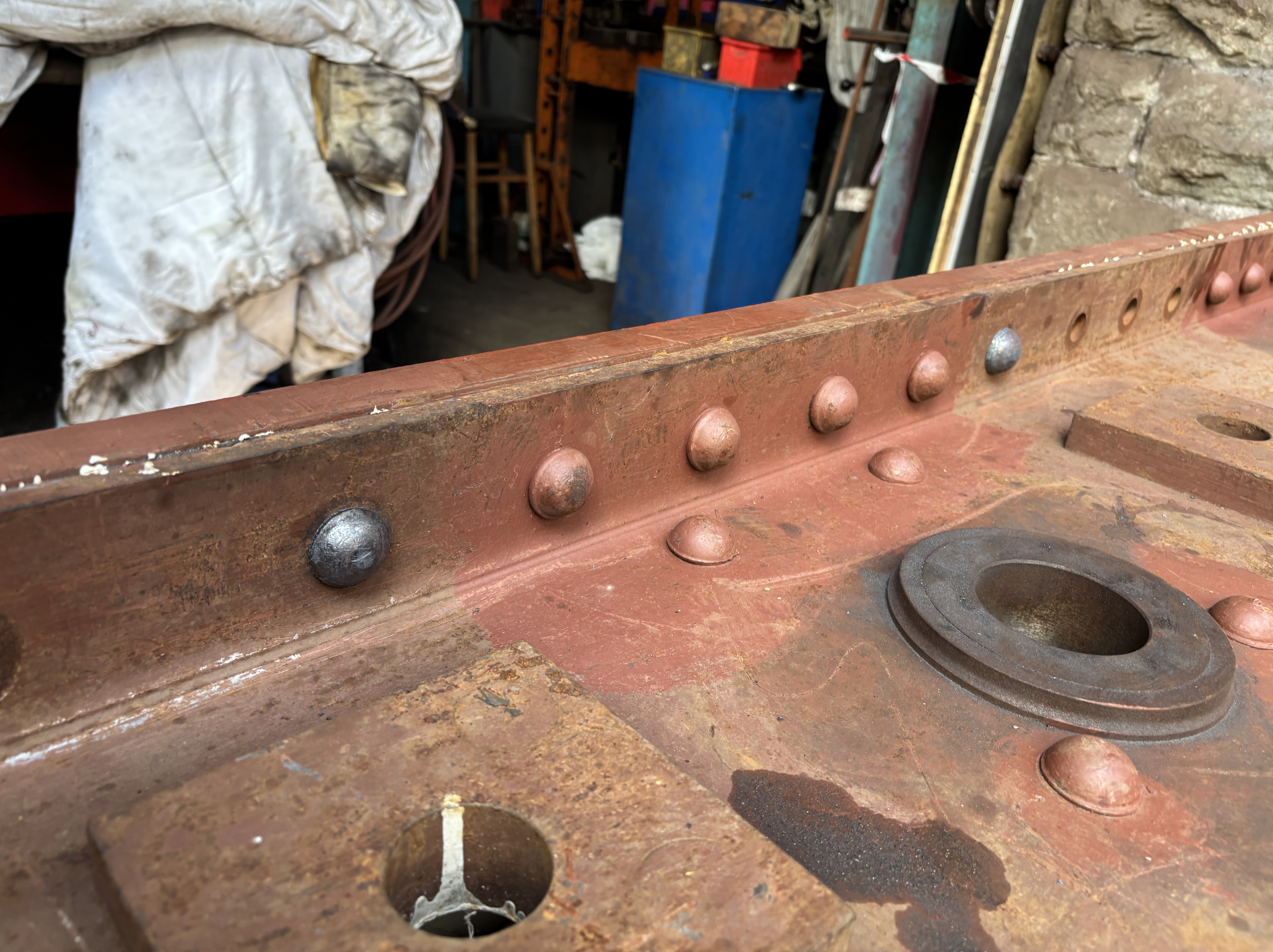
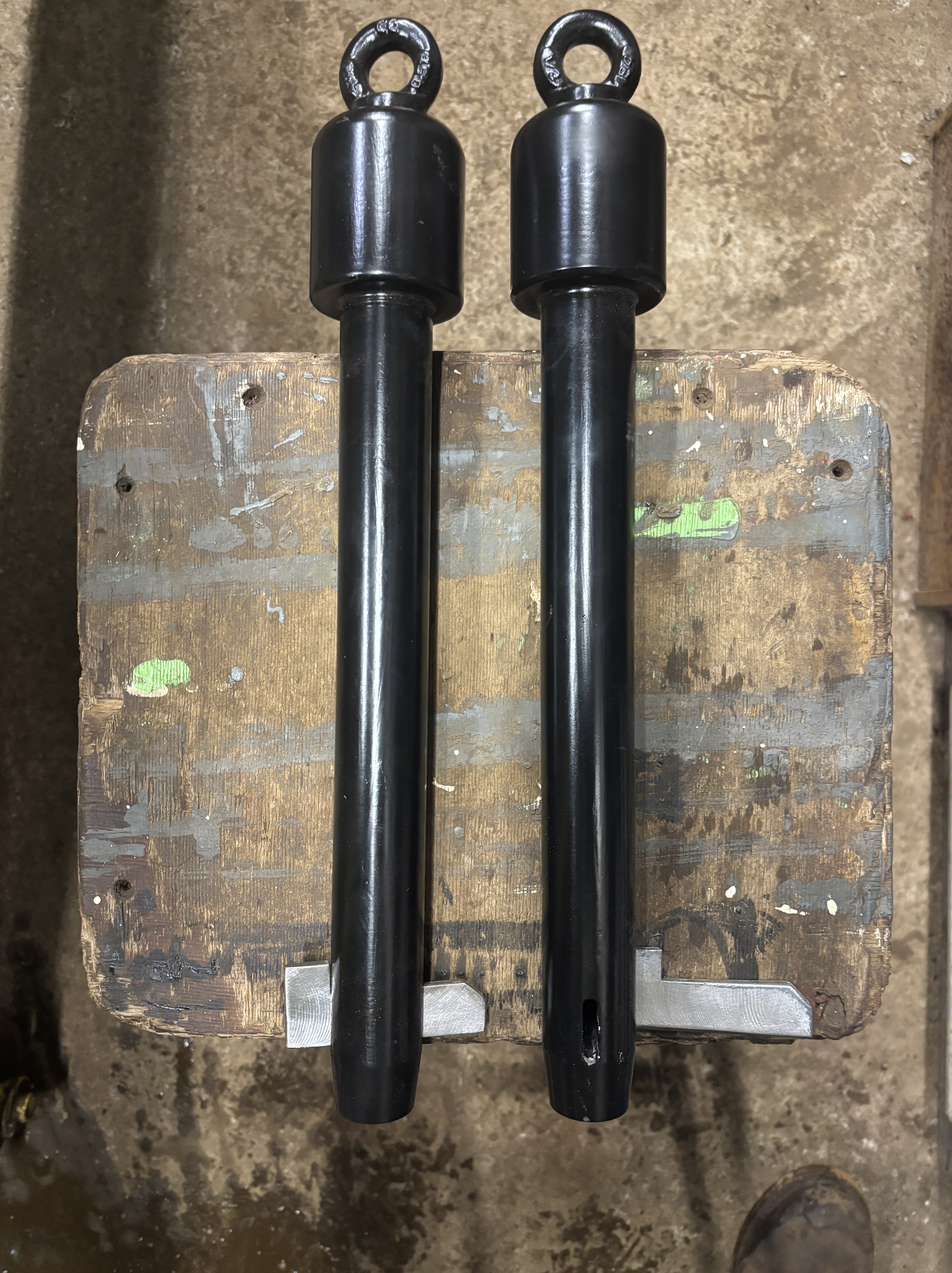
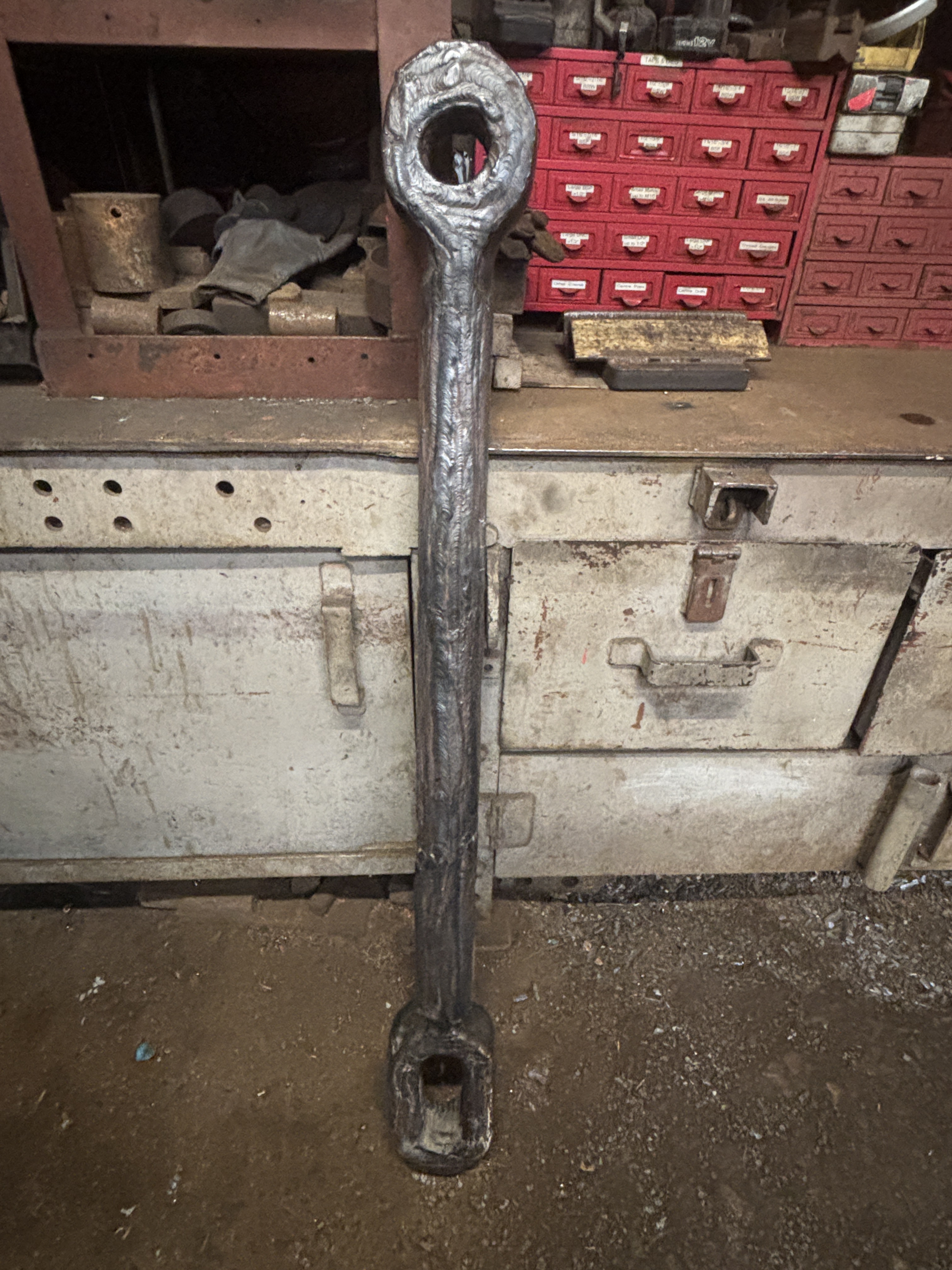
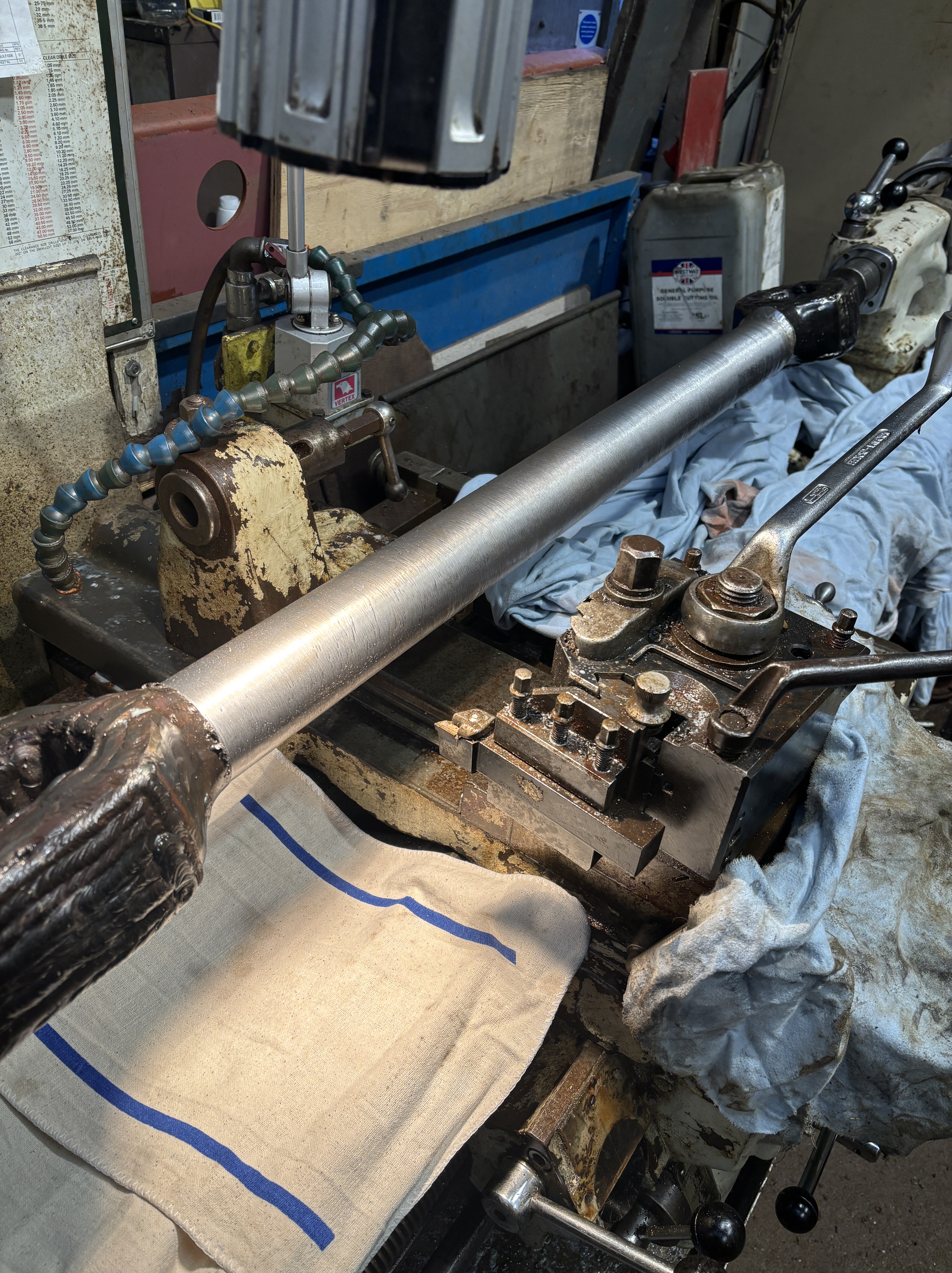
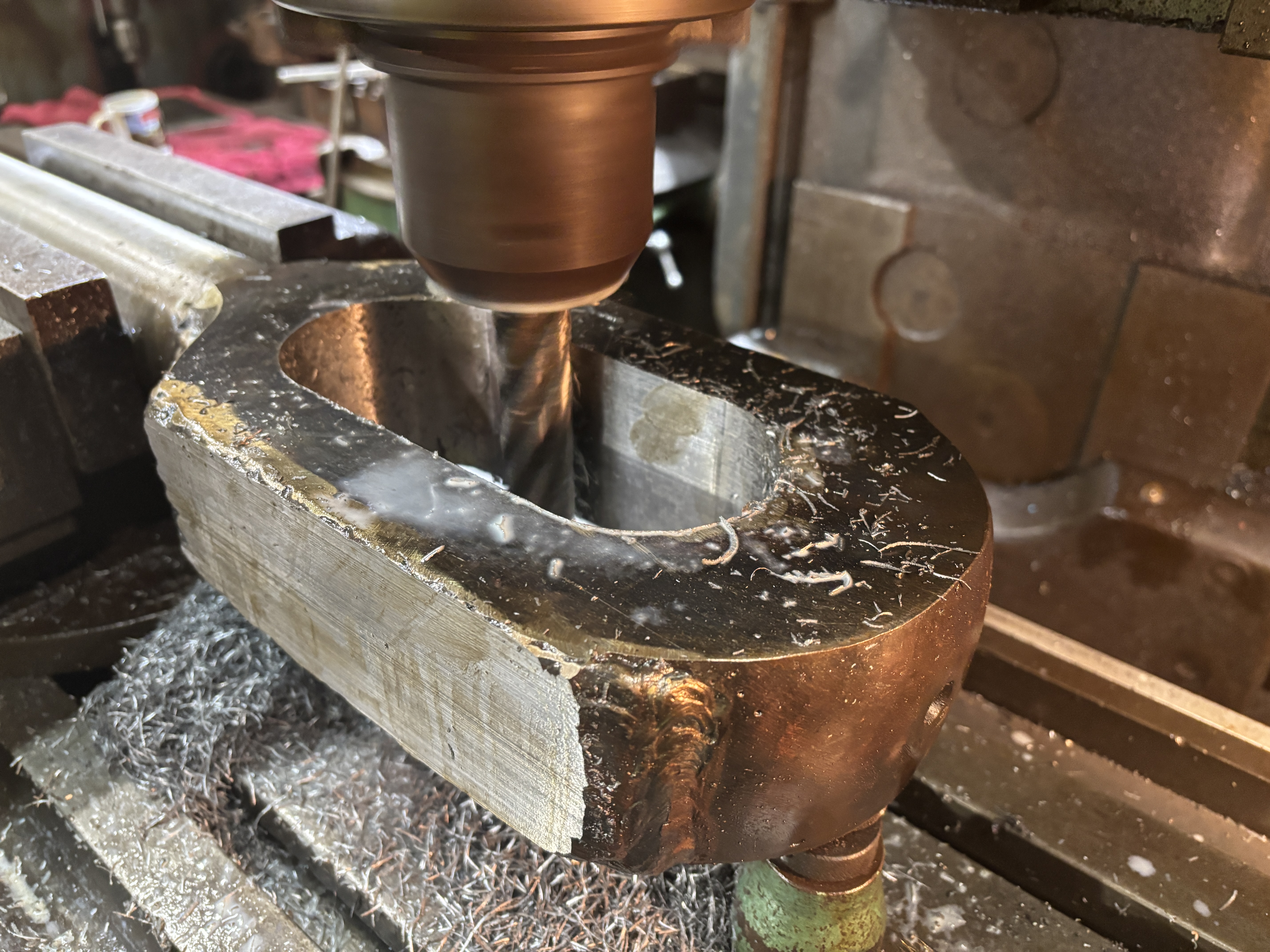
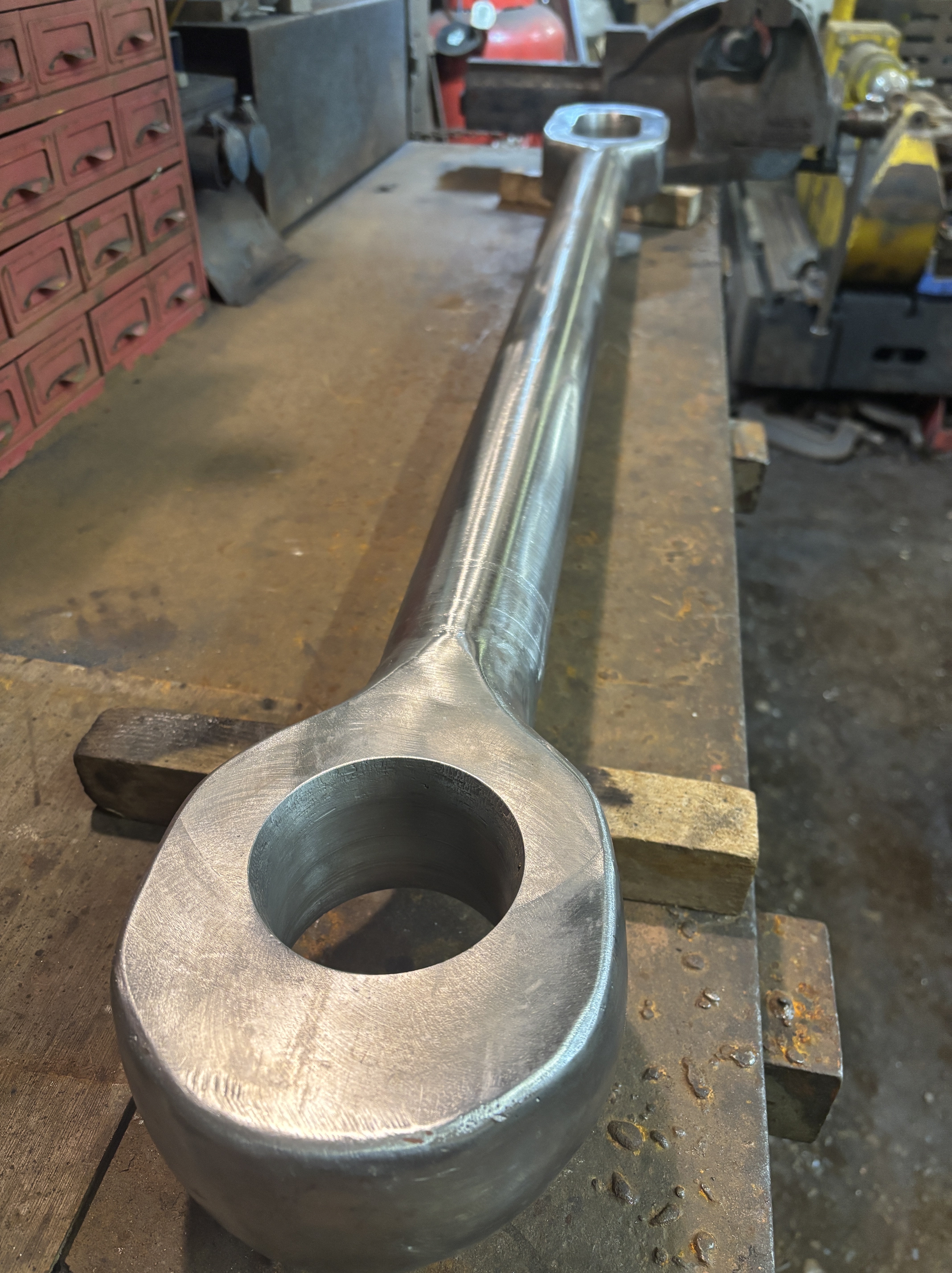
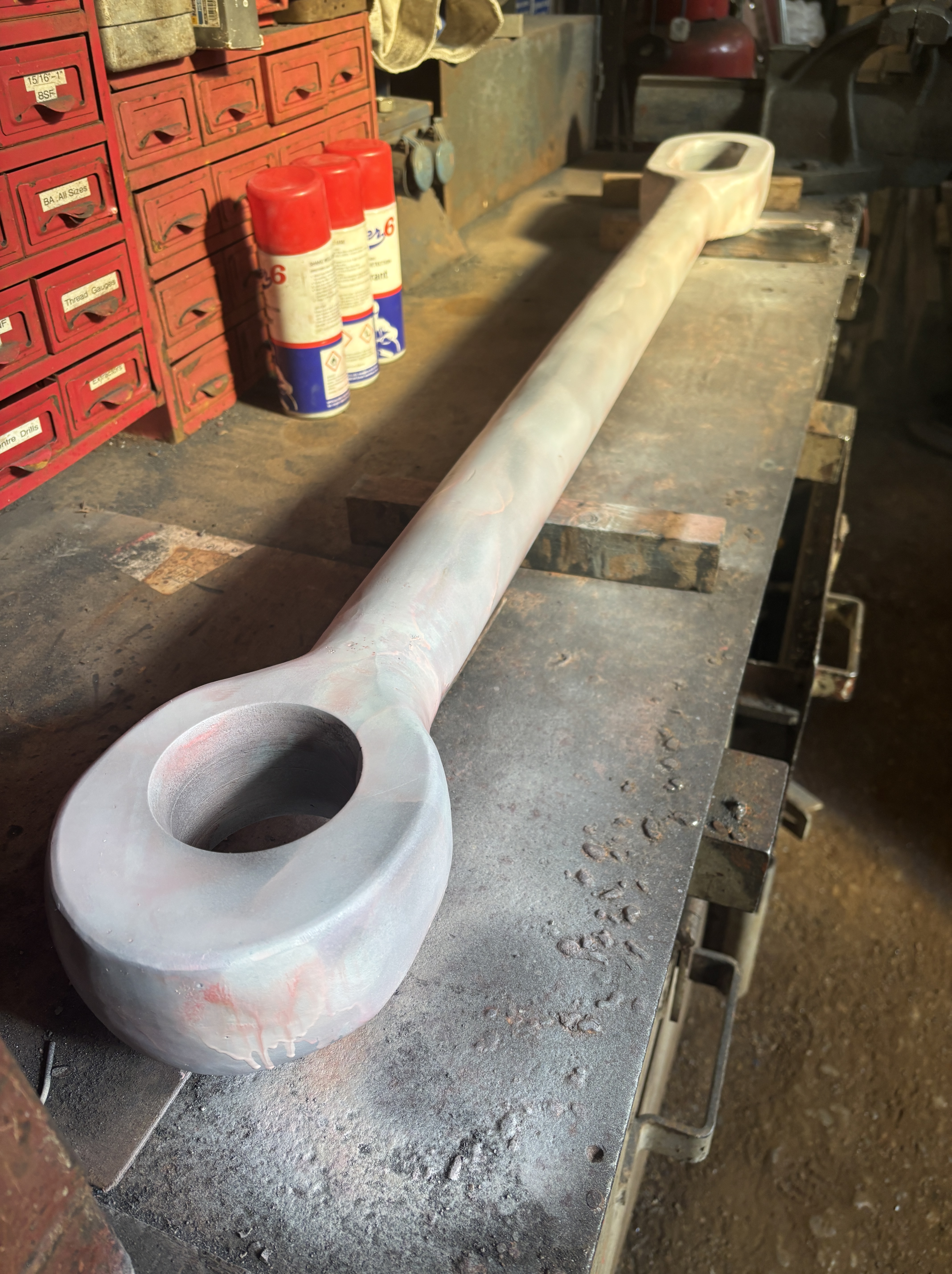
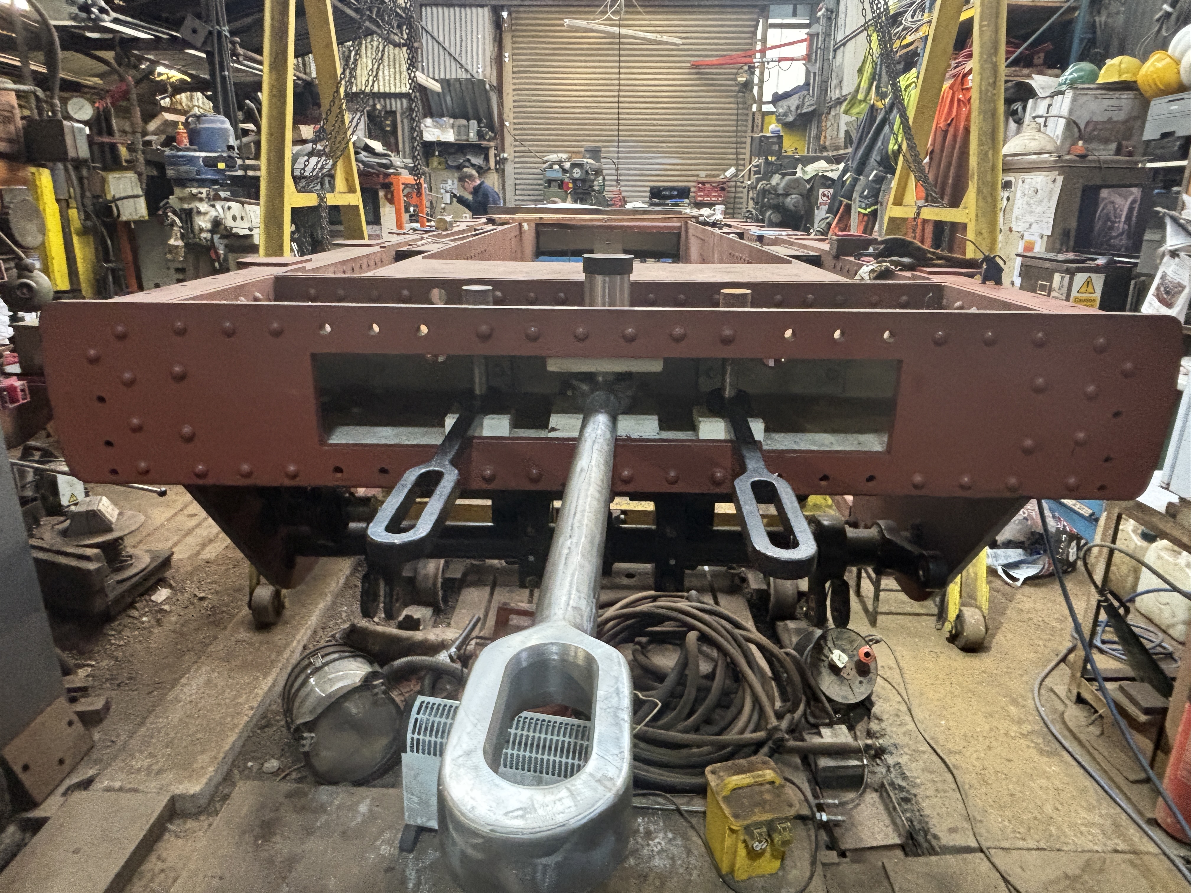
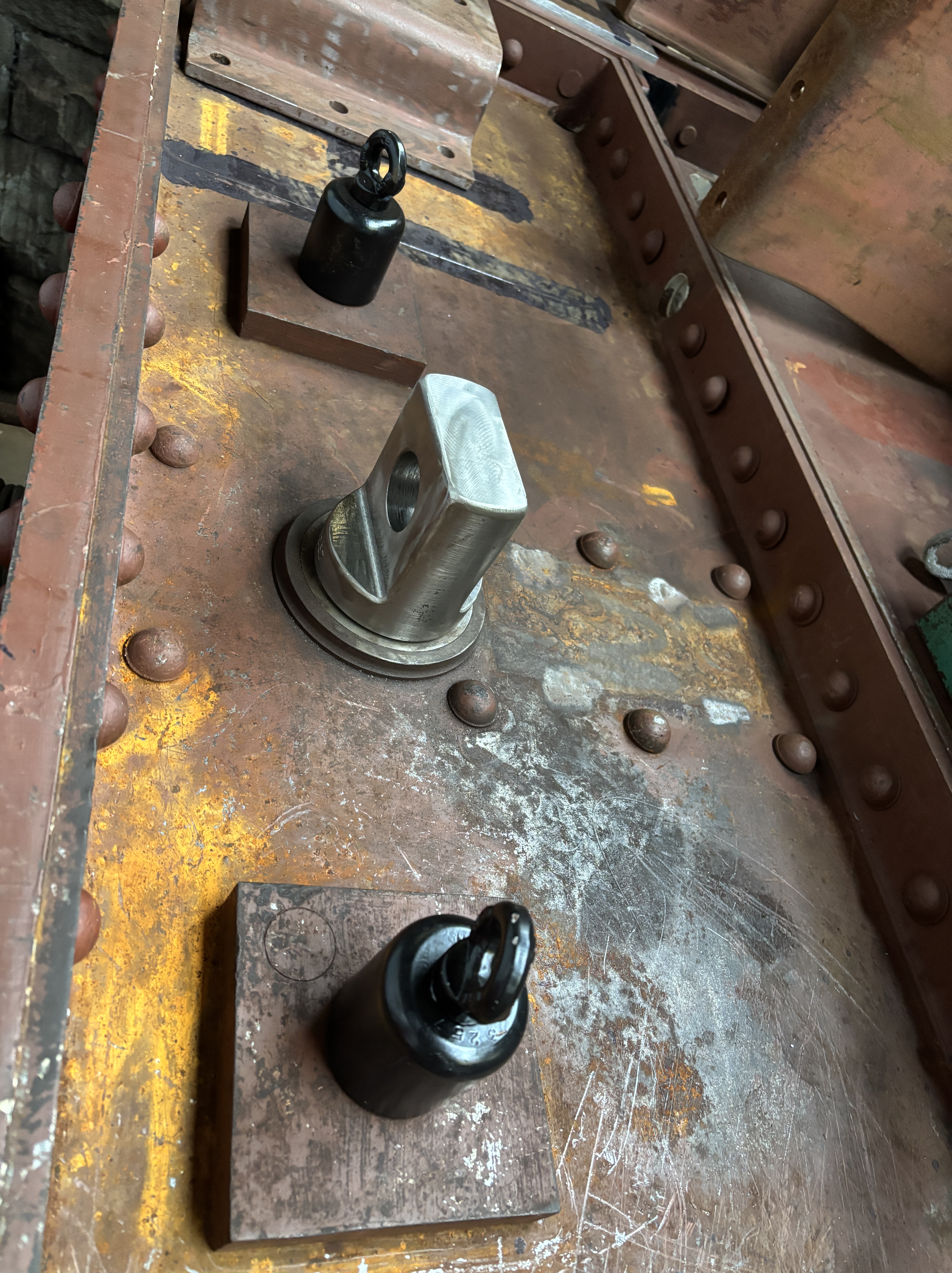
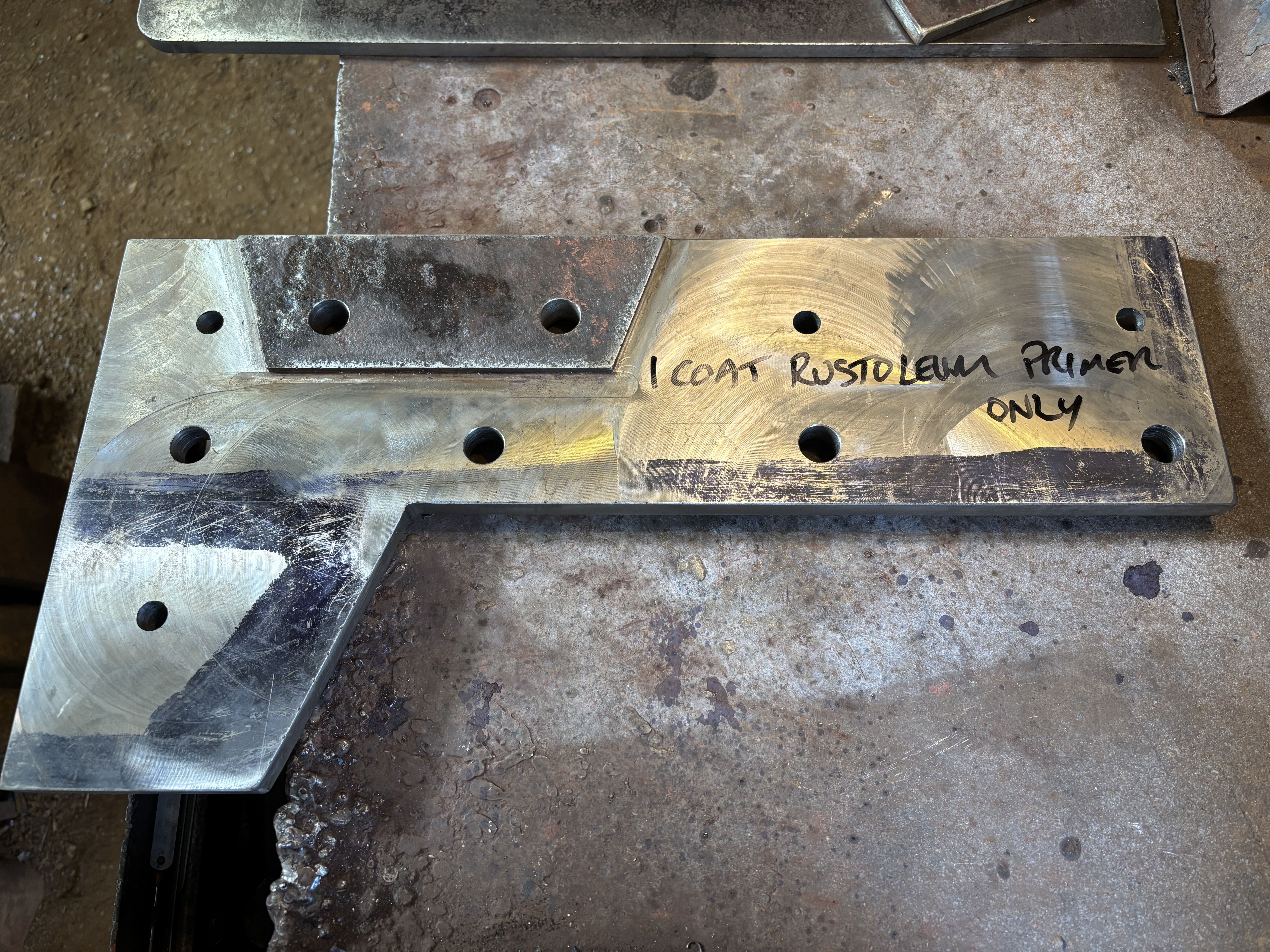
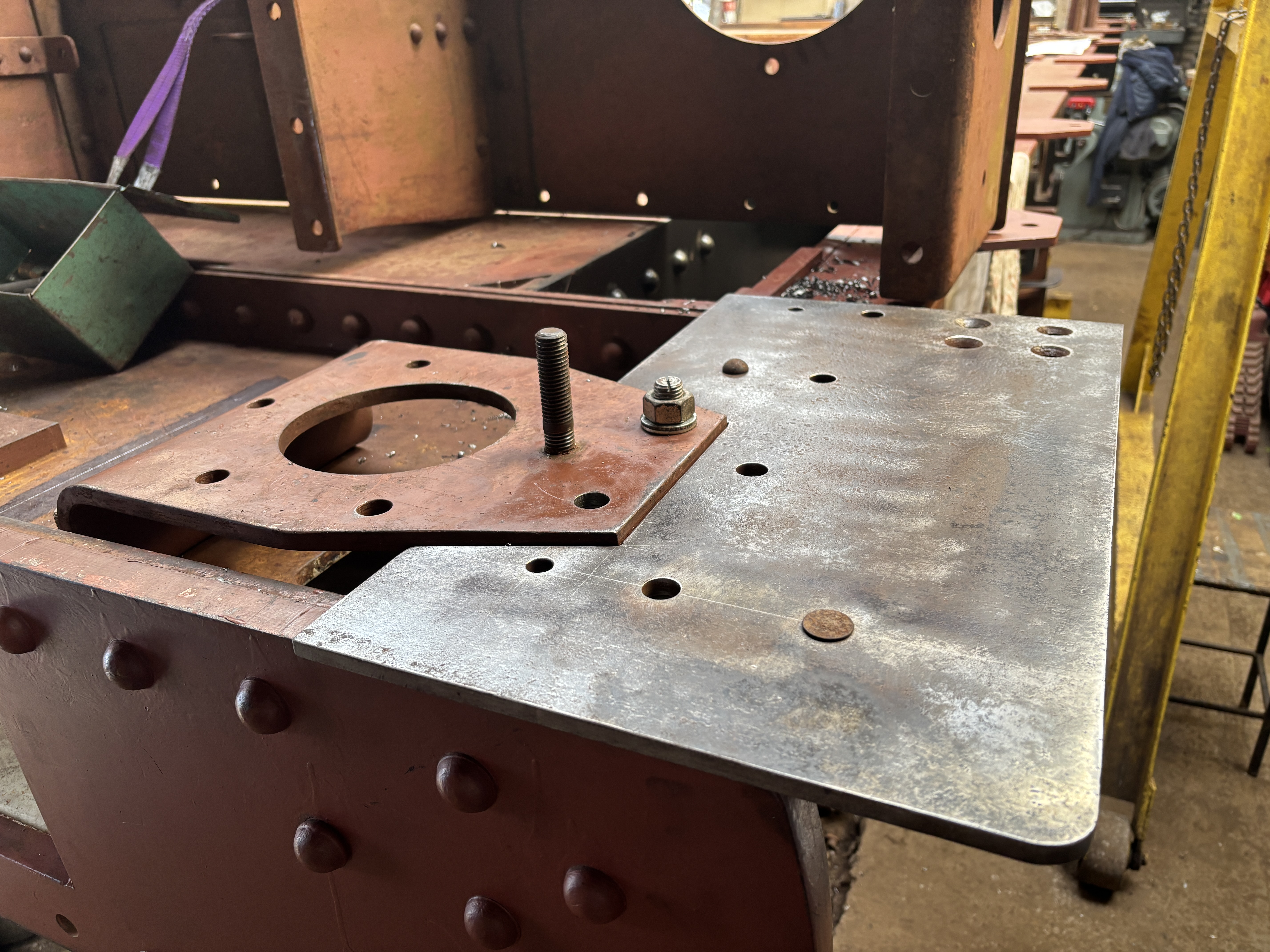
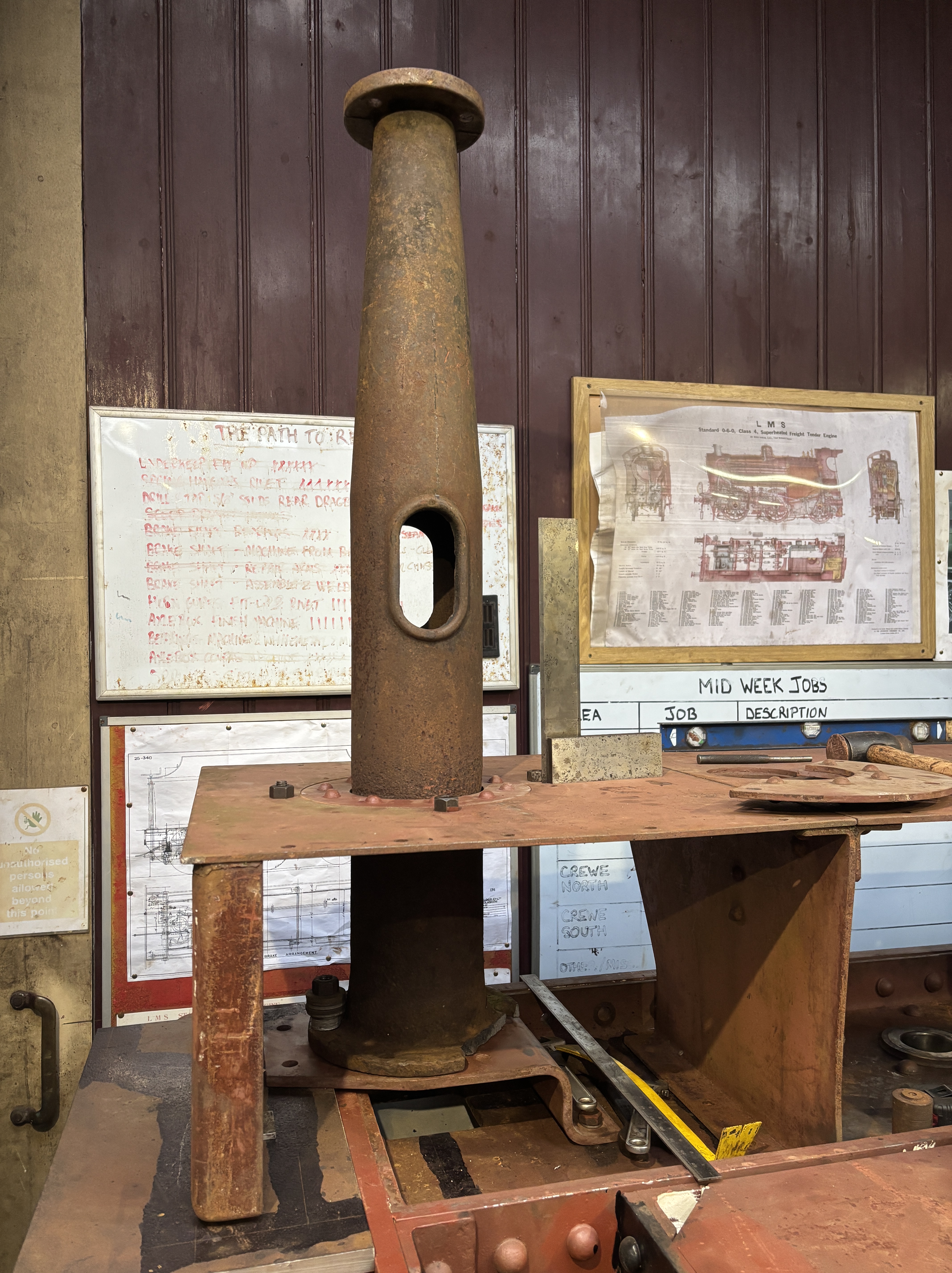
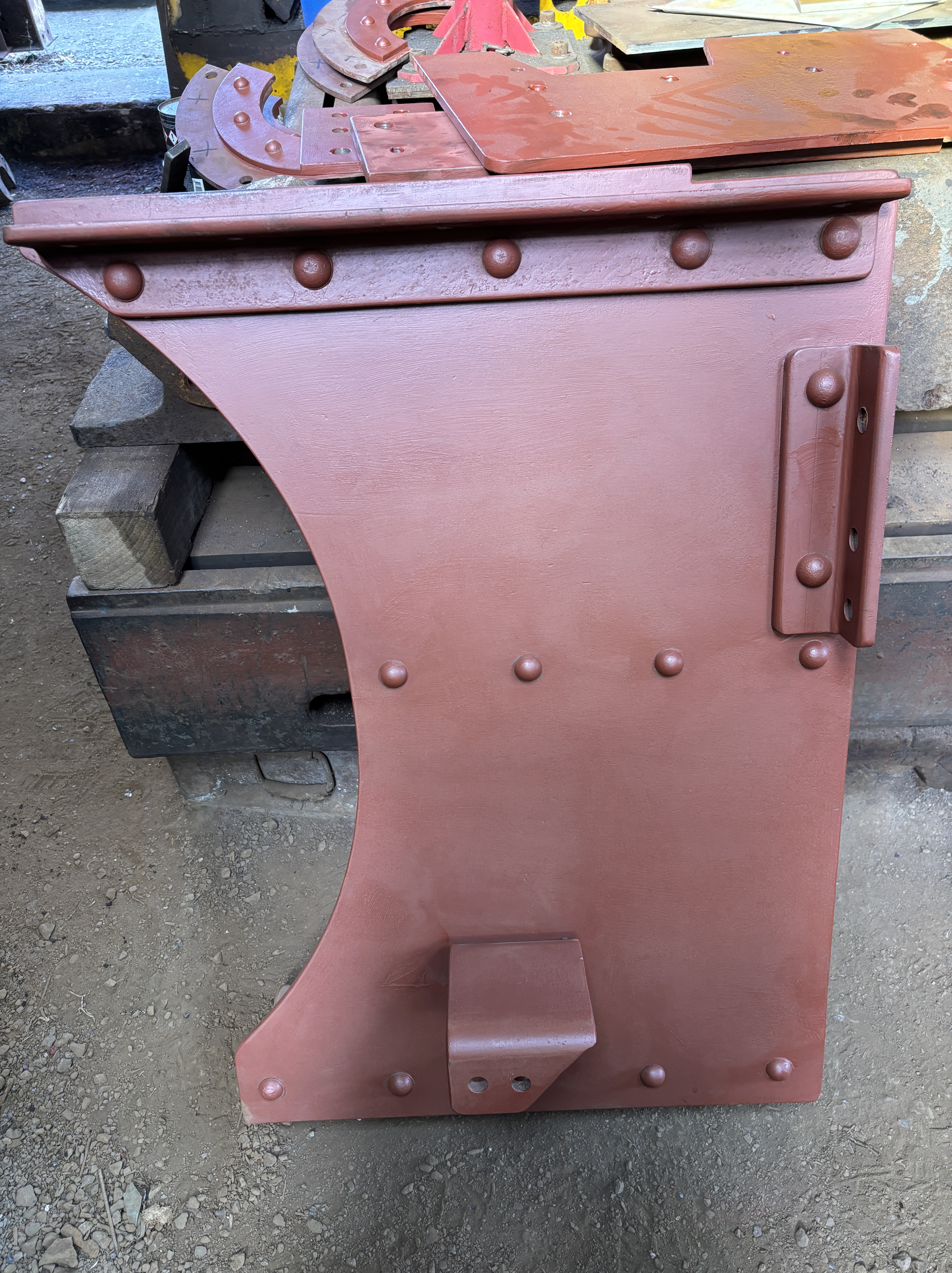
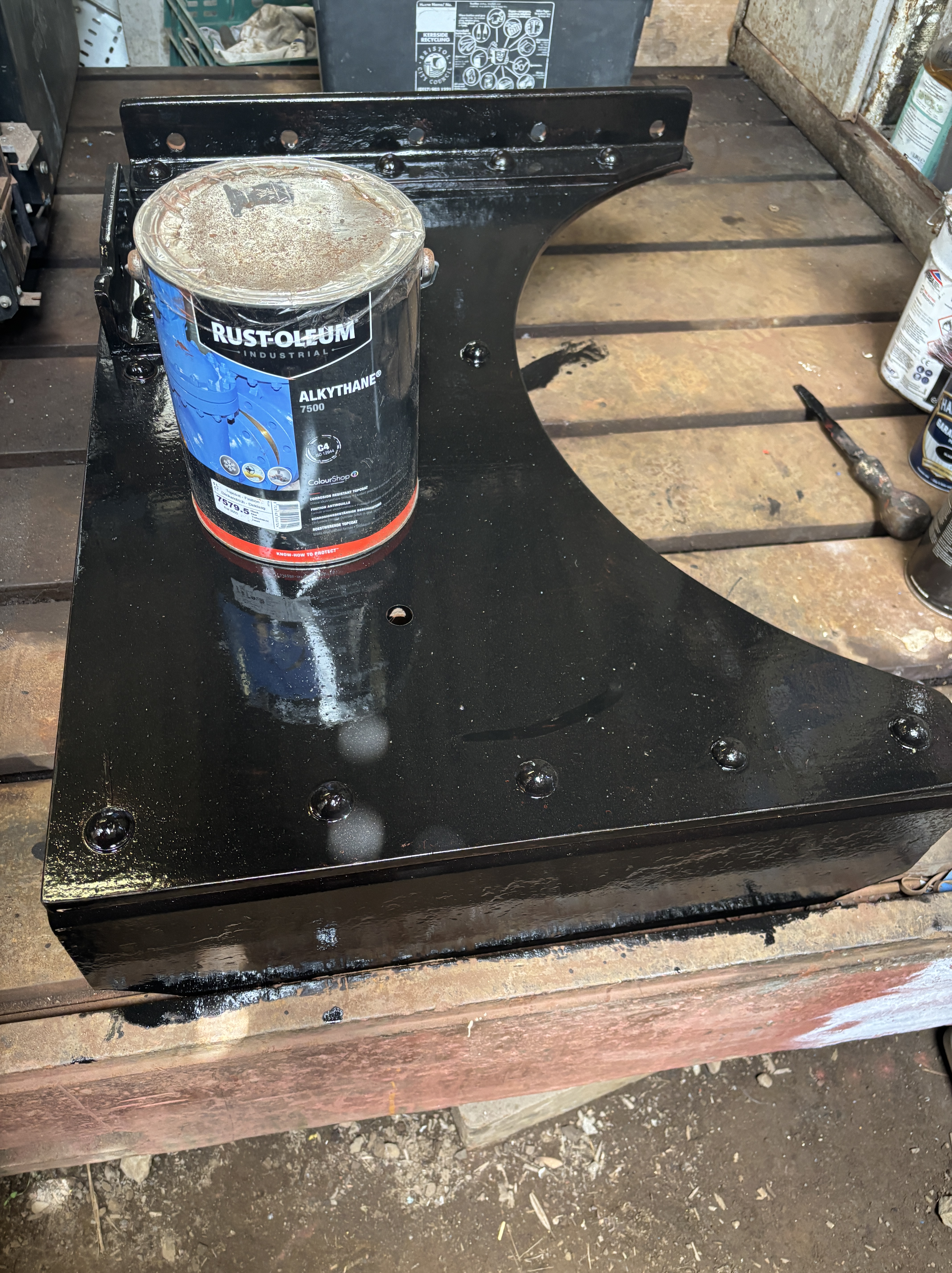
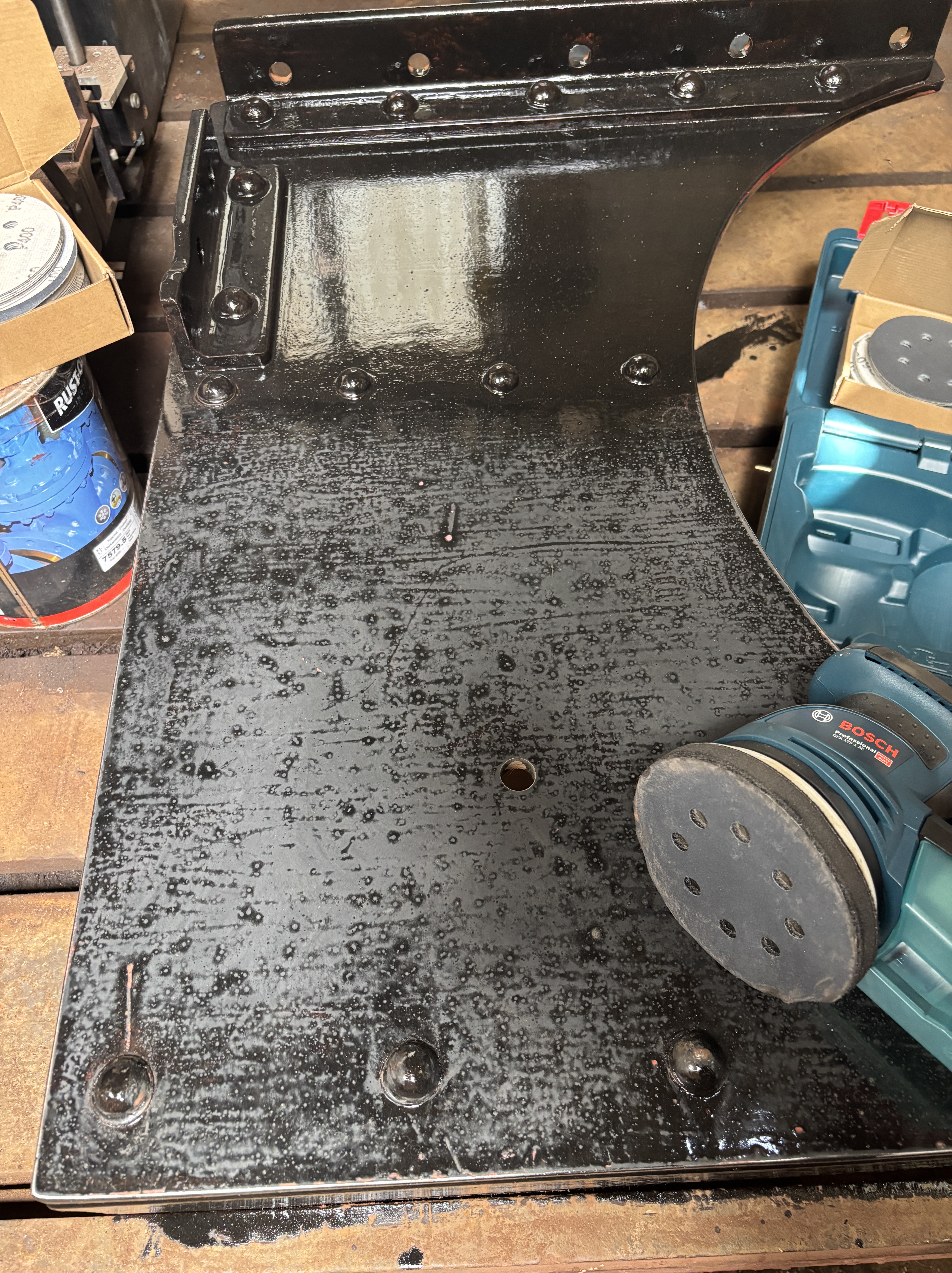
Rivets on the top of the rear dragbox have been ground flushTwo final rivets in the front bufferbeam have been installed. (For various reasons it was just too hard to do these with the chassis upside down!).The tender is coupled to the loco via a large diameter and heavy duty drawbar (more on that downpage), but in addition there are also two “safety links” provided such that the tender won’t separate from the loco if the drawbar fails for whatever reason. (This was not unknown and did happen from time to time, e.g. in the early days of the BR Britannia Pacifics). We have the original pair of safety links, but they are more than somewhat tired and worn out, so it was decided to make new ones. These were profile milled from a solid billet of steel plate. Here we see one of them after marking out.After many hours of work on the vertical milling machine, here we have the two new safety links (in the middle), next to the battered, worn and rusted originals.The safety links are affixed to the front dragbox of the tender by large pins which are inserted vertically. Again, the originals are too far gone to be reused, and new ones were made. Here we see them after painting, and including the two new locking pins which stop them from lifting out. The eyebolts in the head are a modification intended to assist in removing these pins whenever the tender is uncoupled from the loco.The loco-tender drawbar was available but was corroded in places as well as being slightly bent and with worn slot and holes. This has been built-up with weld to restore the original dimensions, and subsquently machined back to size. Because of the thickness of the material (2.875″) and to ensure no cracking, a strict weld procedure was followed involving pre-heat and use of hydrogen-controlled electrodes, as well as staged welding to minimise distortion. This took a lot of time and a large number of welding rods (around 600!), but was worth the effort.Following welding, the drawbar centre section was machined on the lathe.And the ends were machined on the vertical milling machine to bring the slots back to minimum toleranceHere we see the refurbished drawbar after machining completed.Here is the repaired drawbar undergoing dye penetrant inspection to check for any cracking (none found!)Here is the drawbar and its two baby brother safety links installed in the front dragbox. A new pin was made for the drawbar, and the top of that can just be seen here.A view on the top of the front dragbox showing the new drawbar pin and two safety link pinsAlso at the front of the tender is a complicated arrangement of platework which holds not only the front steps on to the chassis, but also the front section of tender lower footplating, the sub-frame for the upper footplate and the mounting plates for the handbrake and water scoop stansion pipes. After much head-scratching over the complex tender chassis drawing, the dimensions of the platework were worked out, and profile milled from 20mm thick plate. Here we see one of these plates prior to painting.Here is the other plate on the LHS of the chassis – this is the lower section of footplate which will marry up with that of the tank when it is dropped into place. One may also see the joggled semi-triangular plate which holds – on the LHS – the handbrake stansion pipe in position. This is all just a trial setup prior to riveting all this together. Here is perhaps a more explantory image showing the whole setup. We are on the LHS of the chassis looking forward and we see the lower footplate, the handbrake stansion support plate, one of the original handbrake stansions (in position temporarily pending delivery of new castings), as well as the footplate/sub-frame assembly in position. Eventually the enginemens’ boots will be standing on the surface where the steel set square is sitting. Hopefully you get the idea….The tender has steps in each corner to allow the enginemen to climb up both into the loco’s cab, and also the back end of the tender. These are extremely heavy duty being made from 1/2″ thick steel plate with substantial treads, all riveted together. Four new steps for our tender were made many years ago, being riveted in our hydraulic press. Here we see the back side of the front left hand set of steps.Here is the back side of the rear LHS steps after a first coat of black topcoat. Painting thinigs in our workshop is never ideal due to the dusty floor. However, this first pair of steps is providing the opportunity for our painting team to practice obtaining a decent finish by use of wet and dry paper in between coats. Here we see the first coat of black being cut back to remove a few lumps and bumps (aka house bricks).
Loco Snifting Valves
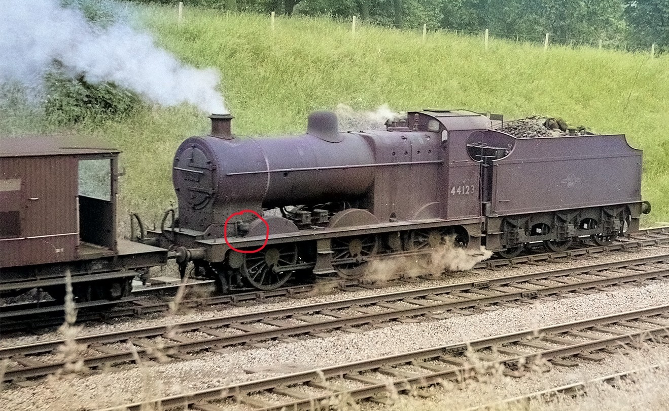
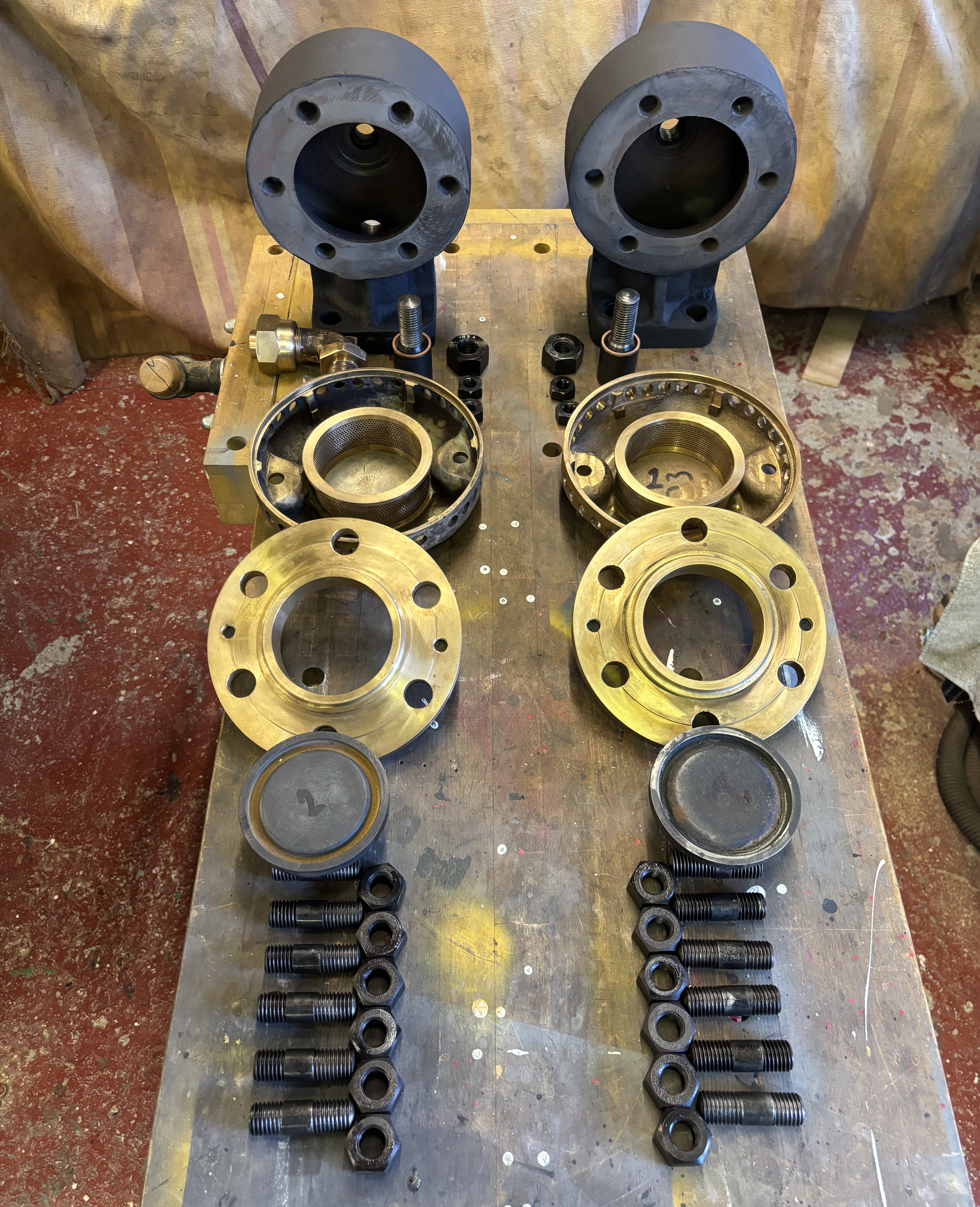
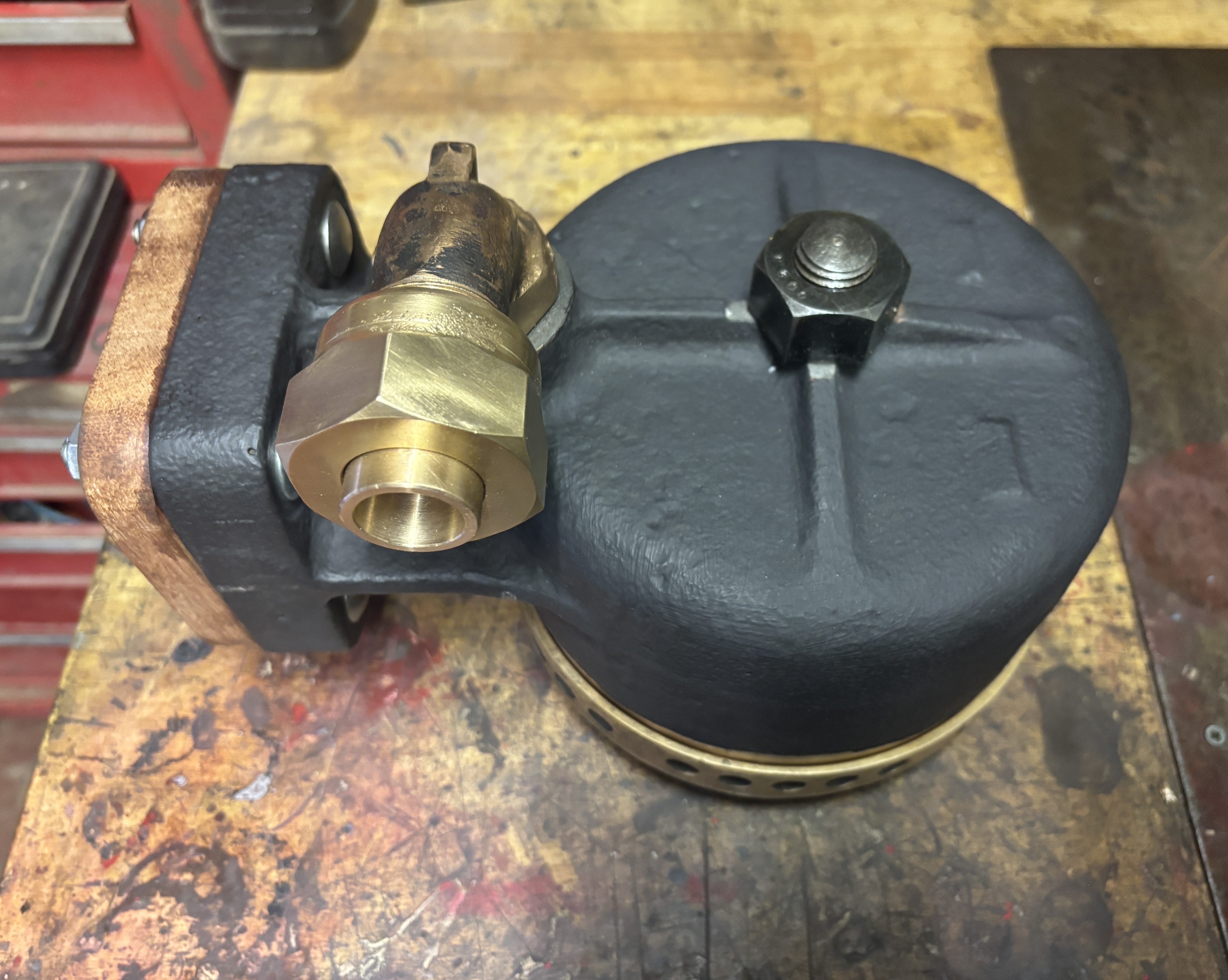
The loco is fitted with ‘Snifting’ valves on the cylinder block. These are a one-way valve that allow air to enter the steam chest when the loco is coasting, with the idea being to prevent a vaccum being created in the cylinders by the reciprocating motion of the pistons, thus avoiding ash from the smokebox being drawn into the cylinders. Like many components on 4123 we had a partial set of bits for the two snifting valves we need, and because no drawing is available, had to back-engineer the internals and details. Finally, after many years of on/off work by our Crewe East machine shop in London, the snifting valves are completed and in store to join the growing list of items being moved from the “to do” list.
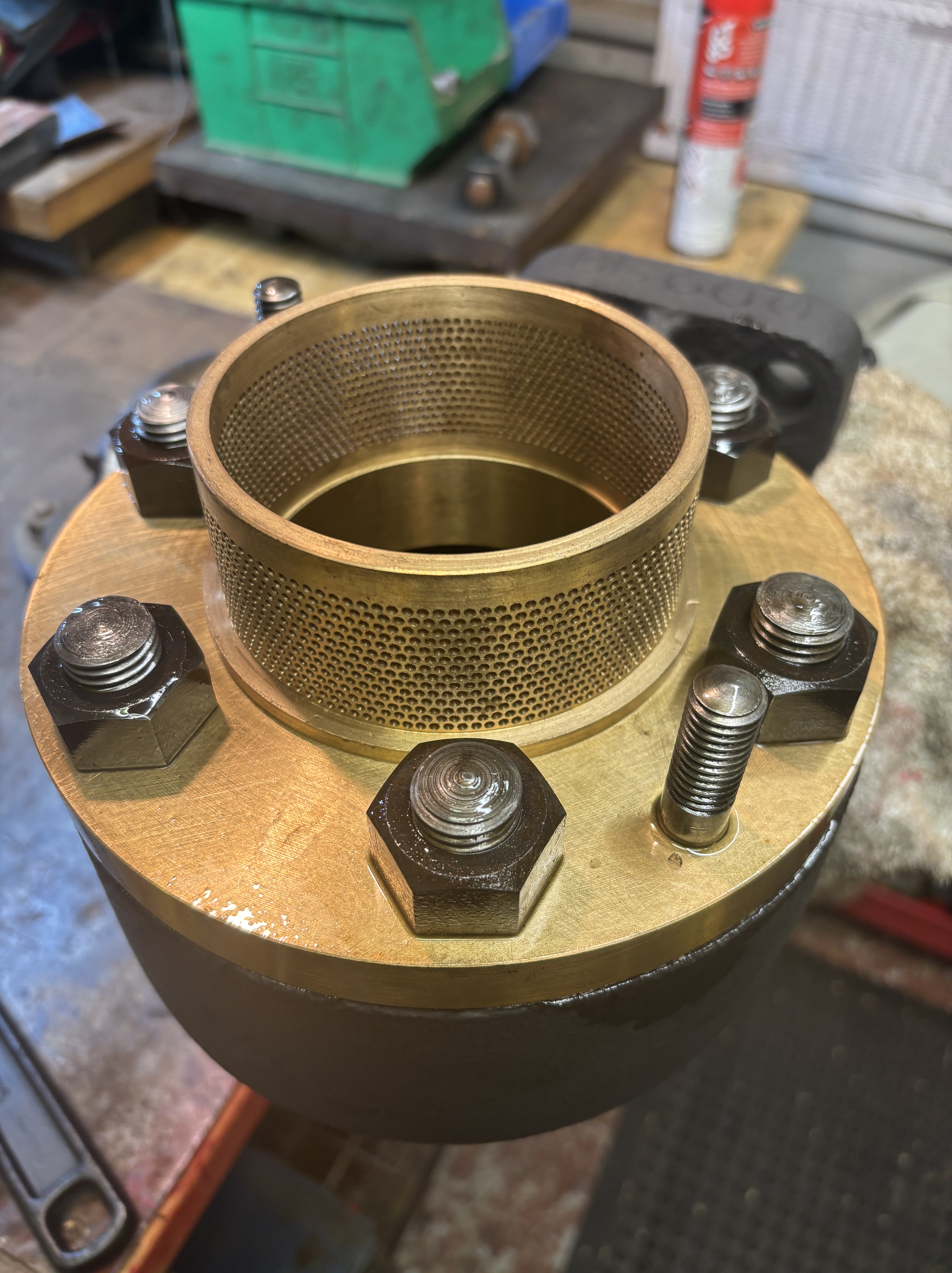
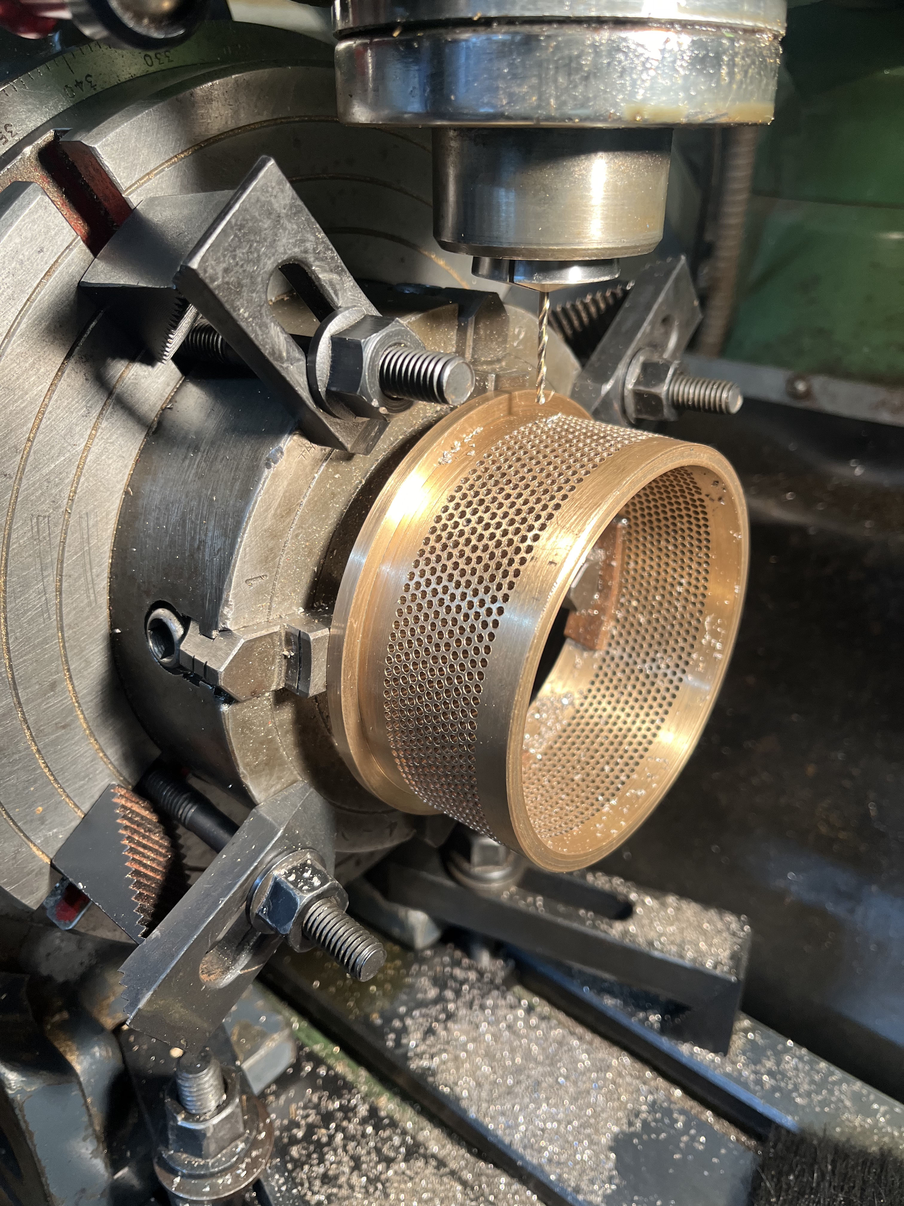
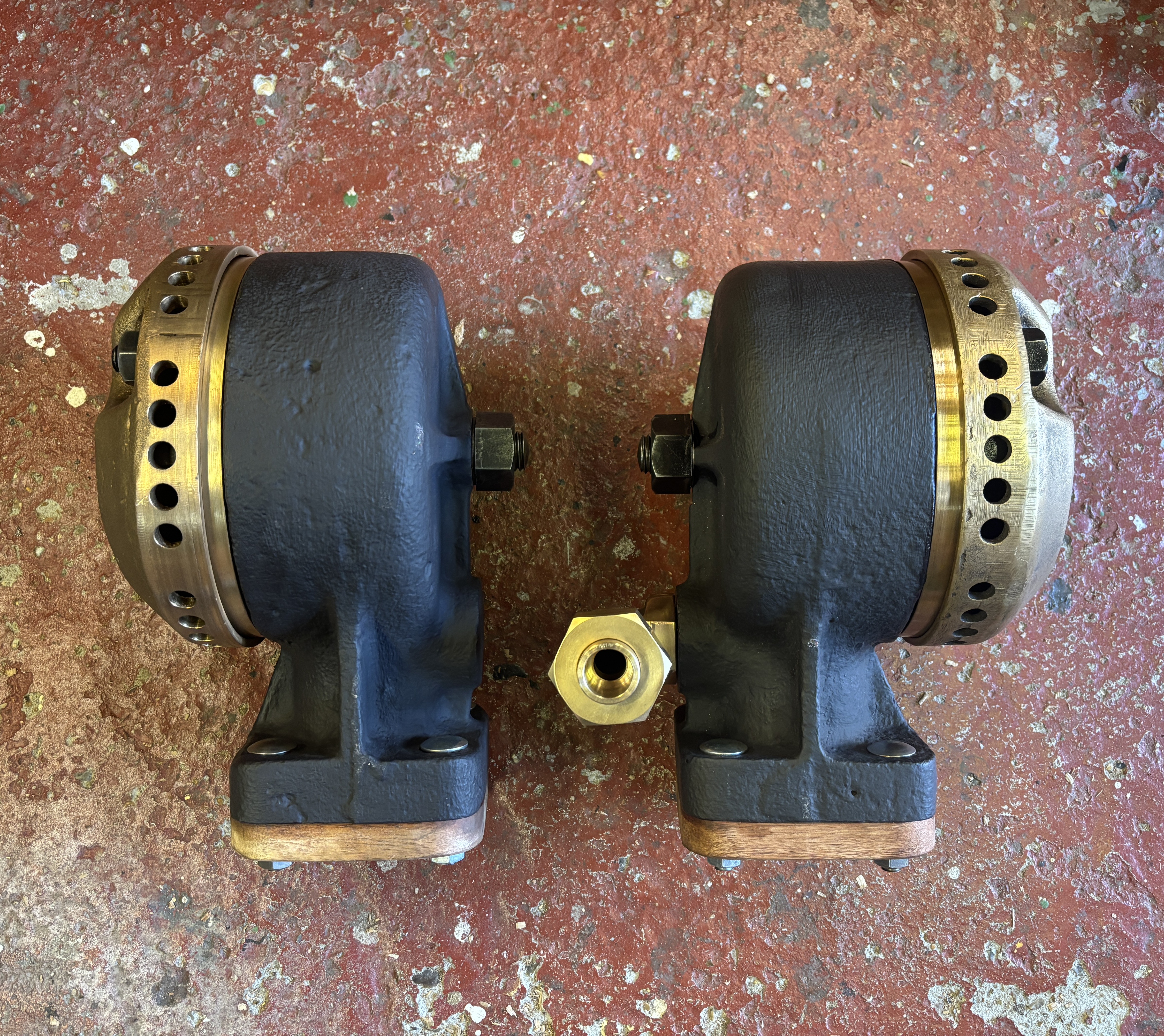
The LHS snifting valve can just be made out on the side of the cylinder block on this wonderful pic of 44123 at Standish Junction on 23rd June 1964. Photo credit Mr Graham Peters.Here we see all the components of the snifting valves prior to assembly. Of the 51 components you see here, only five are original with the rest being newly made.Here is one of the snifting valves during assembly. The ‘pepper pot’ with the holes in is actually a dirt strainer which prevents any large pieces of dirt from the oustide world from being drawn into the cylinders whilst air is being admitted. There are 1,560 2mm diameter holes in this, all of which were drilled manually using a dividing rotary table on a milling machine – so that’s 3,120 holes in total for the pair of valves – a task very firmly in the “never again” category. One of the pepper pots on the vertical milling machine having its holes drilled. Machinists are requested not to look too closely at the setup for this… but… it worked! No CNC machines involved in this nightmare of a machining job!The finished pair of snifting valves all assembled and fitted with wooden blanking plates to protect the mounting flange face.The LHS snifting valve fully assembled with the body painted in heat resistant black paint. The elbow fitting on top is a steam take-off and is only fitted to the LH valve.
That’s about it for this update. For regular snippets of what we are up to and progress being made on this big restoration project, check out our Flickr account, Instagram, or Facebook Group. Thank you for your attention to this matter!





 The London Midland Society Webpage