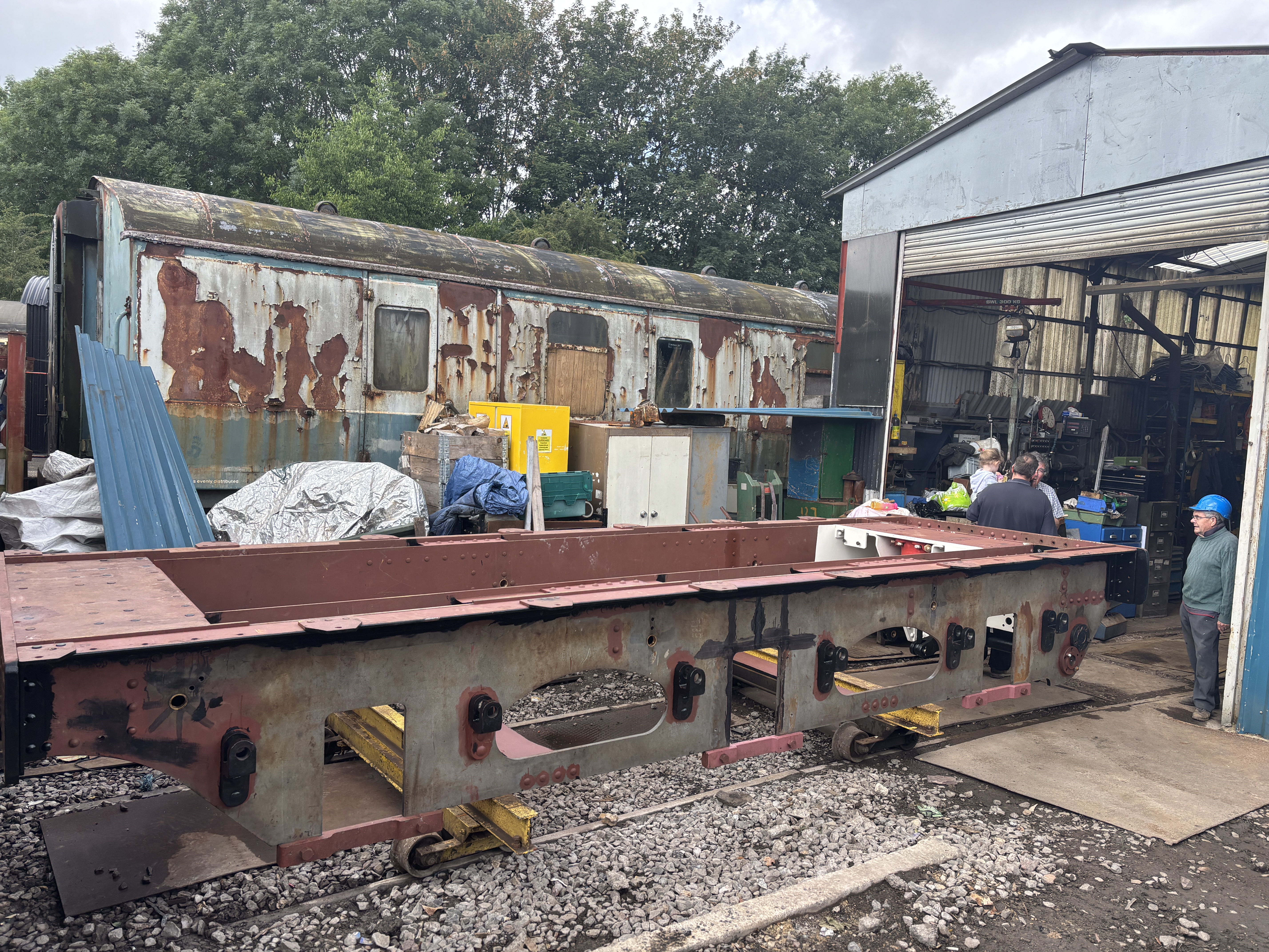
On Saturday 14th June we turned over our new-build tender chassis to get it the right way up so we can finish off the last remaining pieces of work before re-wheeling.
Tender chassis in our workshop – constructed upside down for ease of access – but we have done everything we can in this position, and it needs to be turned over.
At this point, the chassis weighs approximately 5 tons, so obviously turning it over with our 2 ton gantry crane in the workshop is a non-starter – even if there was room to do so. This meant that the chassis needed to be moved outside. The easiest way of doing this would be to roll it out via the AVR goods shed, and transport it by rail into the yard. However, because of other priorities, the AVR wasn’t able to support this move, so we had to go out the other way, via our roller door. Unfortunately, this meant moving our largest machine tool – a DeVlieg Jigmill out of the way a little – an operation which required jacking it up and moving it backward by about 10 inches so that the chassis would be able to squeeze by.
The following series of pictures show how we got the chassis out of the workshop and turned it over.
The chassis is inched out of our shed on its accomodation dillies. Traction provided by the AVR’s forklift.Forklift getting ready to haul the first ‘train’ that the tender chassis was part of.
Once the chassis was outside, the opportunity was taken to complete some more of the painting on areas which would be inaccessible or harder to paint when it was the right way up.
Chassis parked outside so the painting team can progress with more paint.The rear dragbox area after attention by the painters. White for the areas which will be hard to see into and inspect when the chassis is in service.
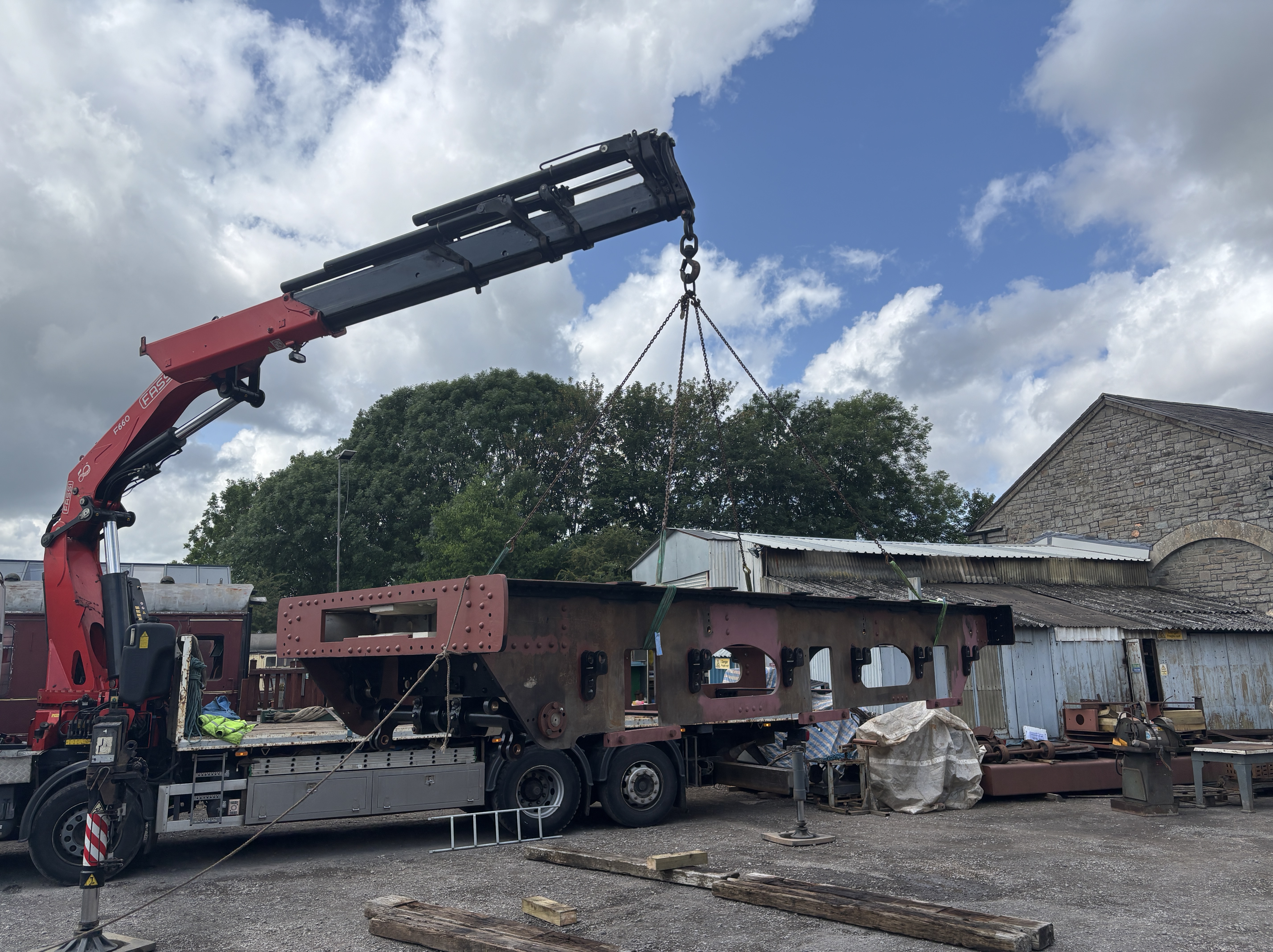
The day of the lift saw us hiring in a very large truck-mounted crane (or Hiab) to lift the chassis into the AVR yard which is nice a flat and has plenty of space for such an operation. To ensure a safe operation, we carried out a full risk assessment and method statement – writing it all down enabled a few things to be thought through and adjusted prior to commencing work.
A test lift to weigh the chassis on the crane’s load scale, and get it hanging level-enough to commence the main lift into the car park.The chassis – still upside down – temporarily landed in the car park
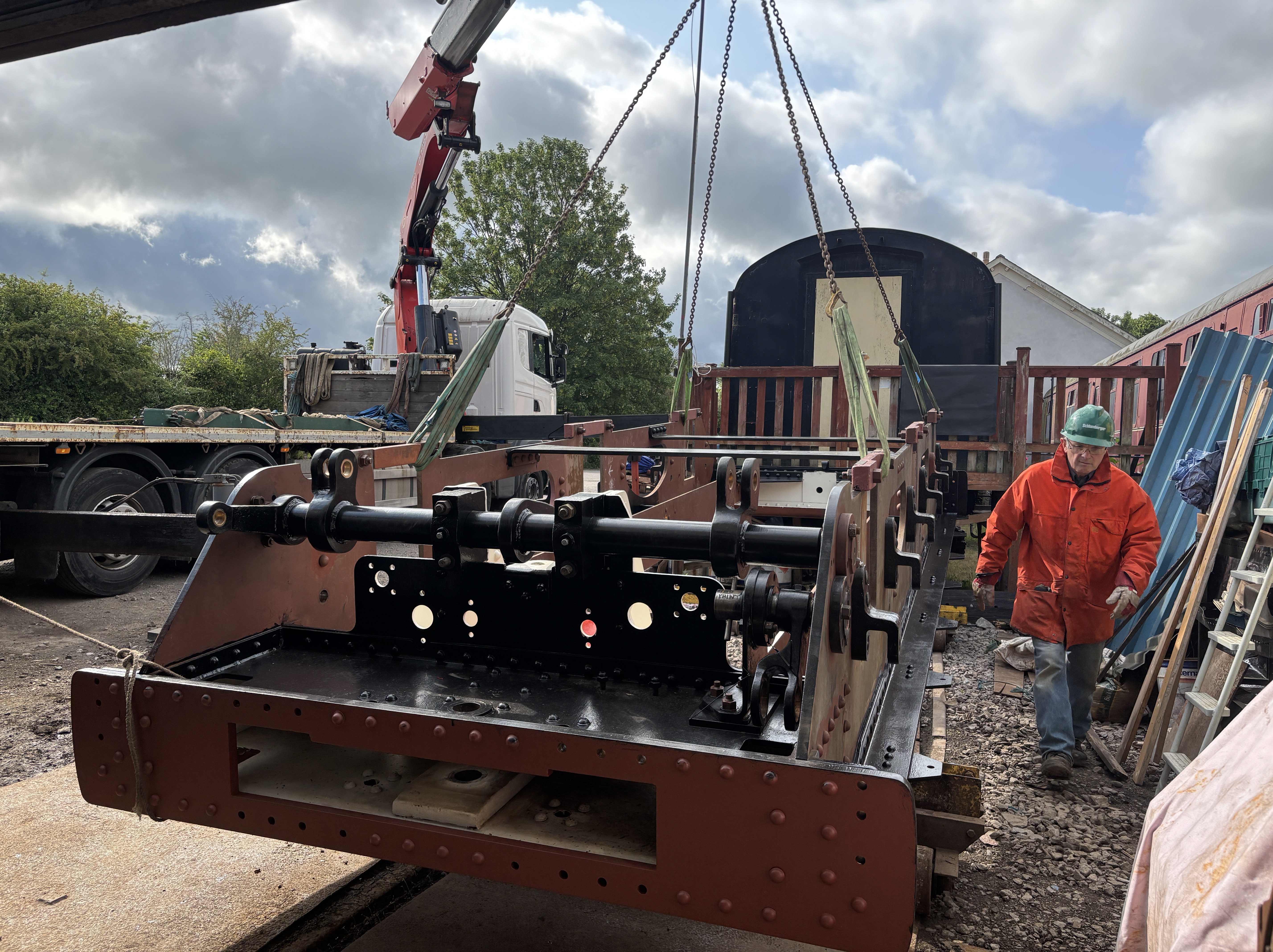
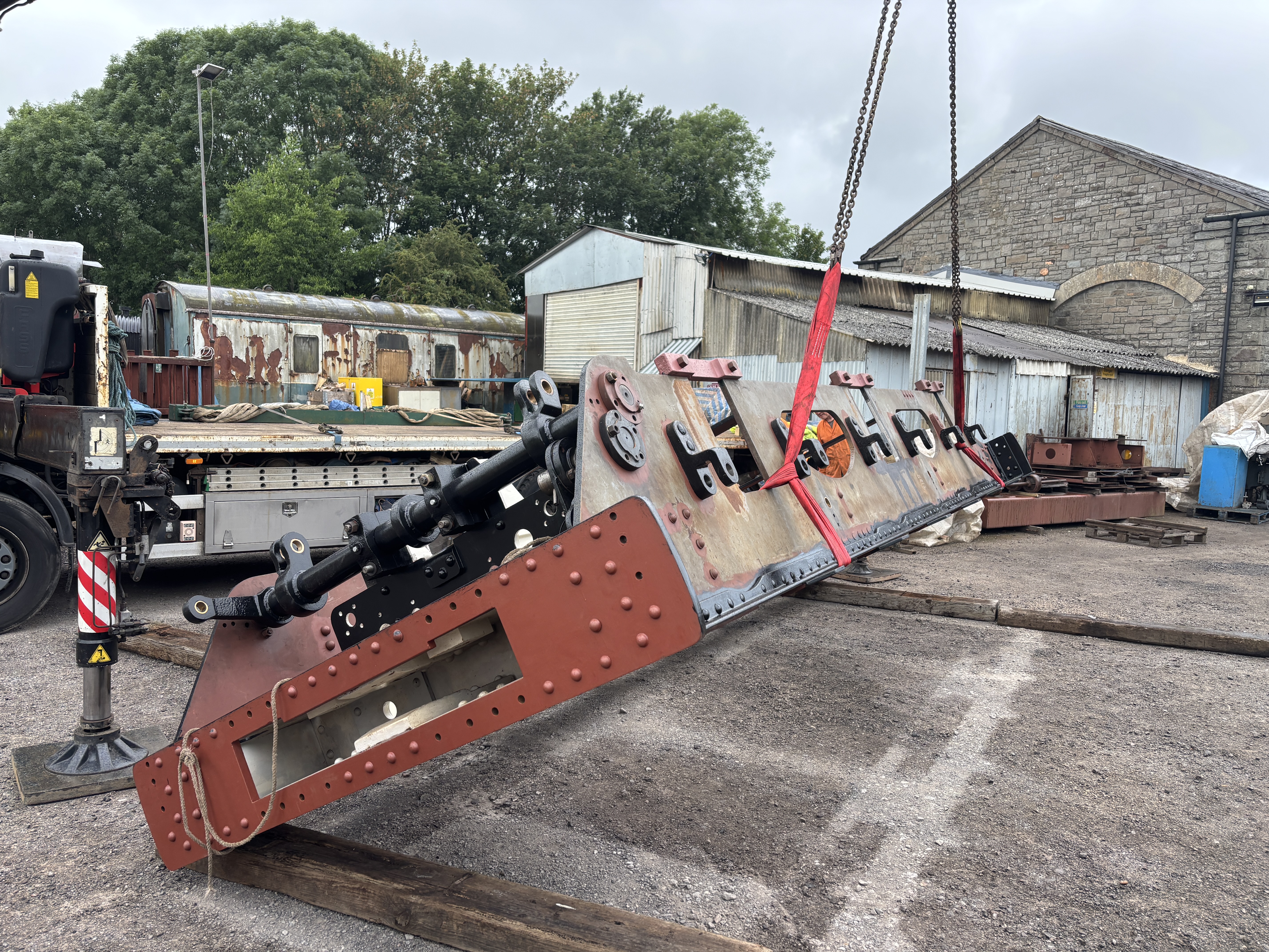
Up she goes – the chassis being lifted on one side to commence turning it over.
Up on its side, and ready to lower back down the right way up.Coming back down to a landing on wooden sleepers (which are there to provide a bit of ground clearance as well as something for the chassis to bite into and pivot around).Now the right way up, the chassis is lifted ready to be swung back towards our workhopAlmost back over the rails and ready to land on the temporary wheels.
Landed safely, and ready to be dragged back inside.
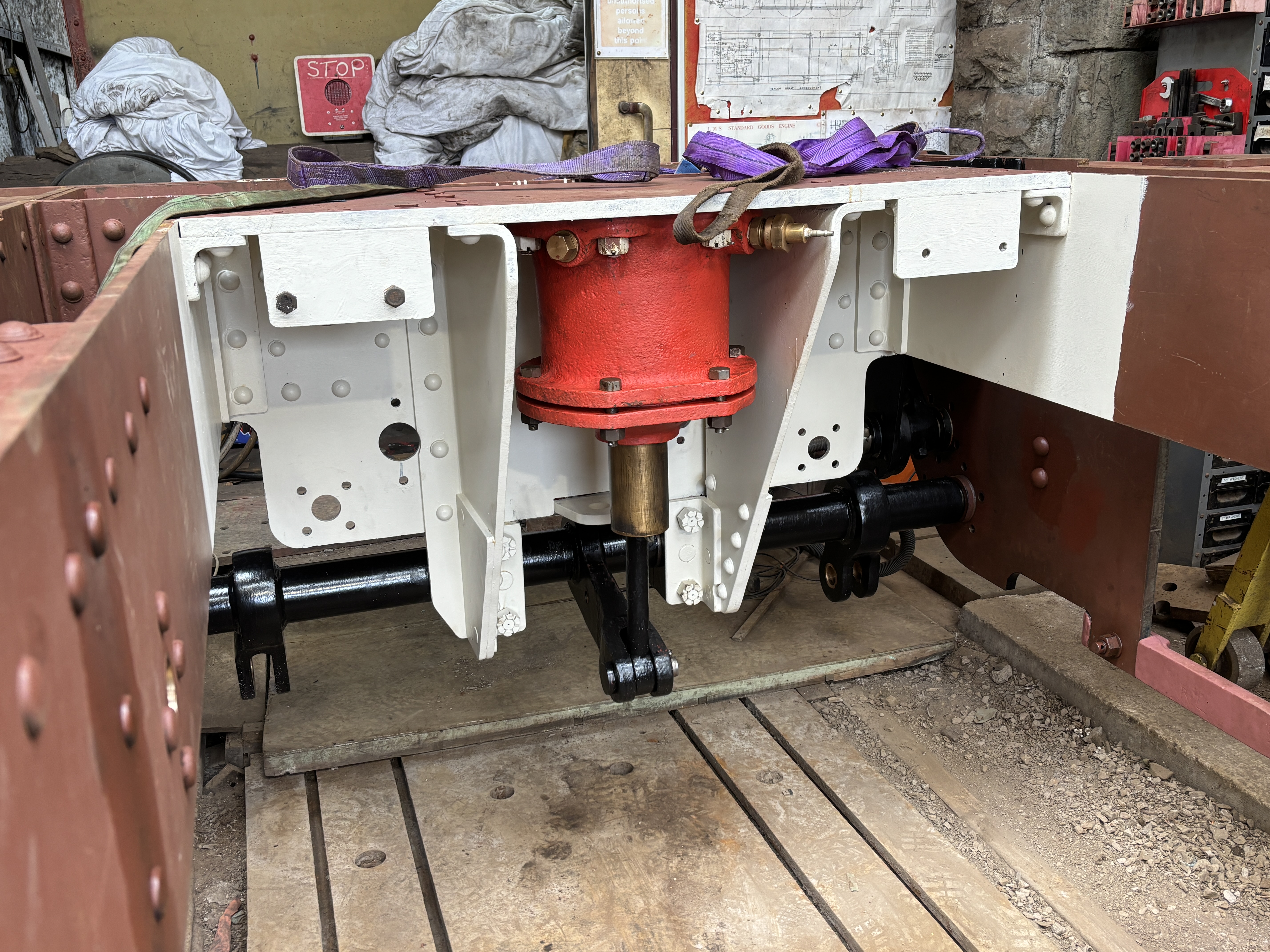
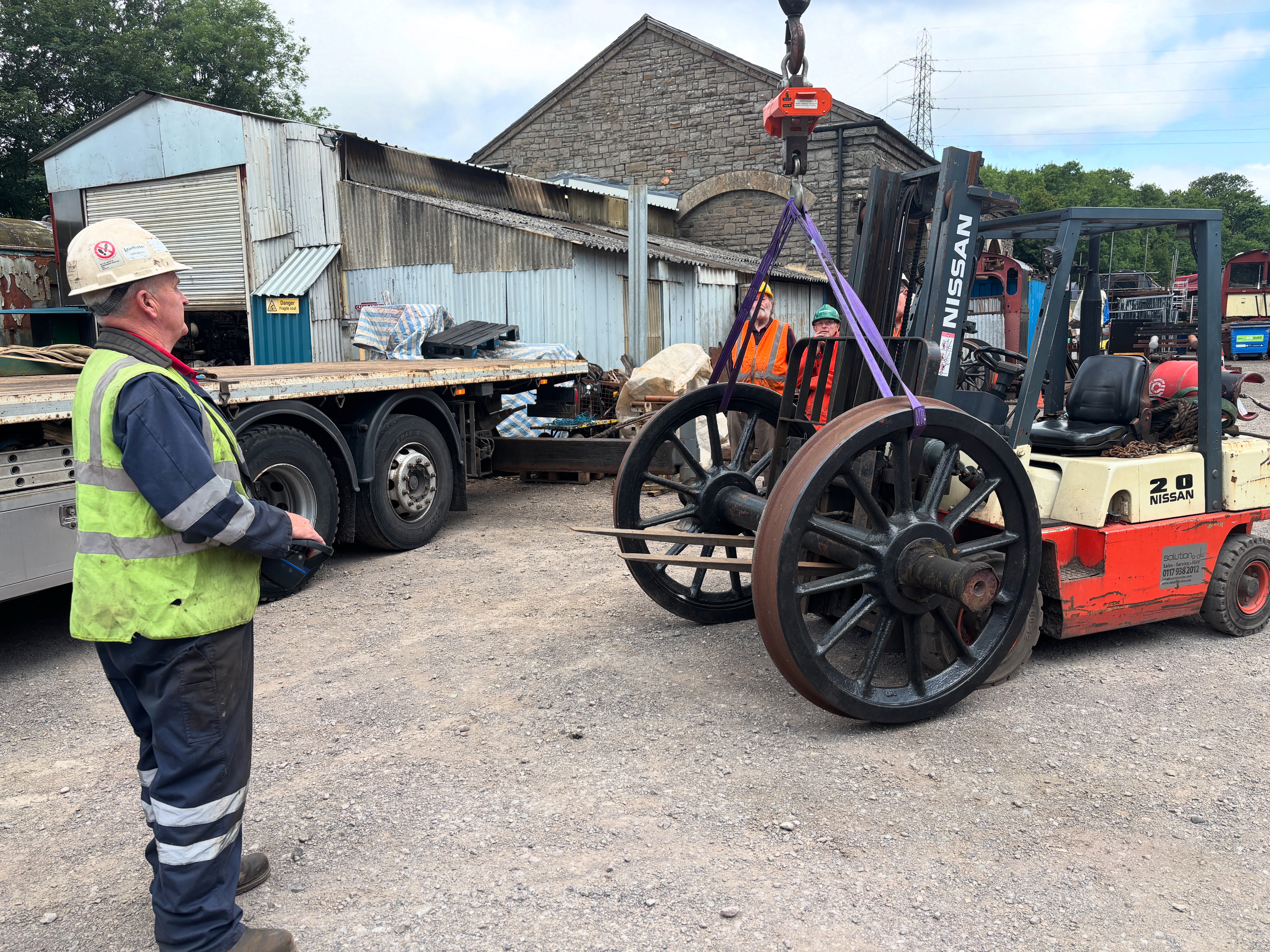
With the chassis the right way up, it’s possible to see what the underneath of the front end looks like. Almost everything seen here is new build or completely refurbished back to new condition.This is the tender steam brake cylinder and its associated steelwork. Again, apart from the cylinder casting, all of this is new material.With the crane on site, the opportunity was taken to weigh one of the tender wheelsets on its load cell. It came in a 1.5Tons exactly.
Going back a month or two before the move outside, and will all the brake hangars and linkages refurbished, we took the opportunity to do a trial fit of the tender brake gear. It all fitted nicely and even operated perfect on air (instead of steam). Although it would have been nice to leave it in place, it had to be removed for the turn over operation – and will also need to be absent when the tender is re-wheeled. Only then can we install it for the final time.
The front-end of the chassis showing the brake gear trial fit. Tender brake links being refurbished, including provision of grease nipples
A view looking towards the rear of the tender showing the brake gear in the process of being fitted up.
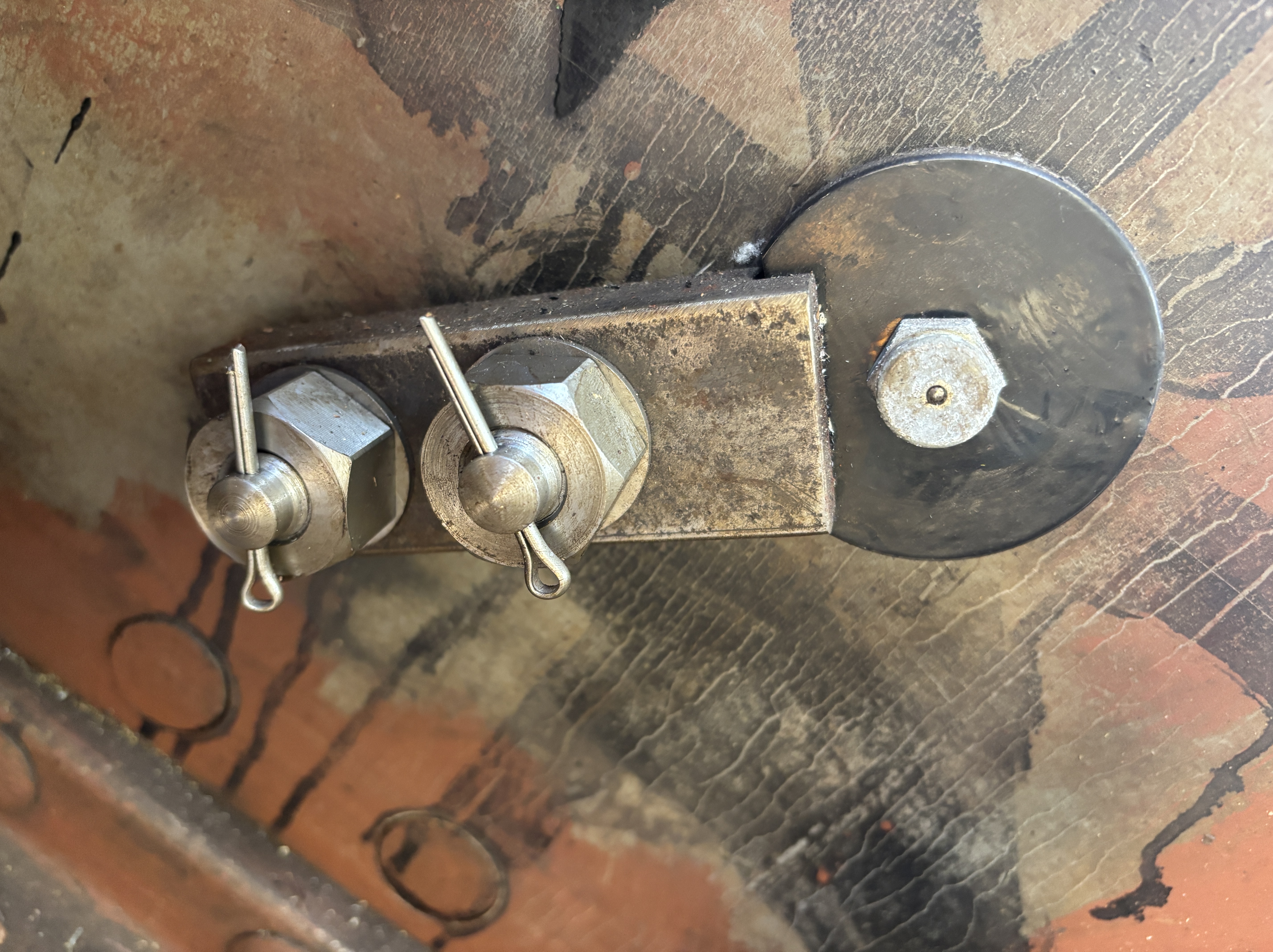
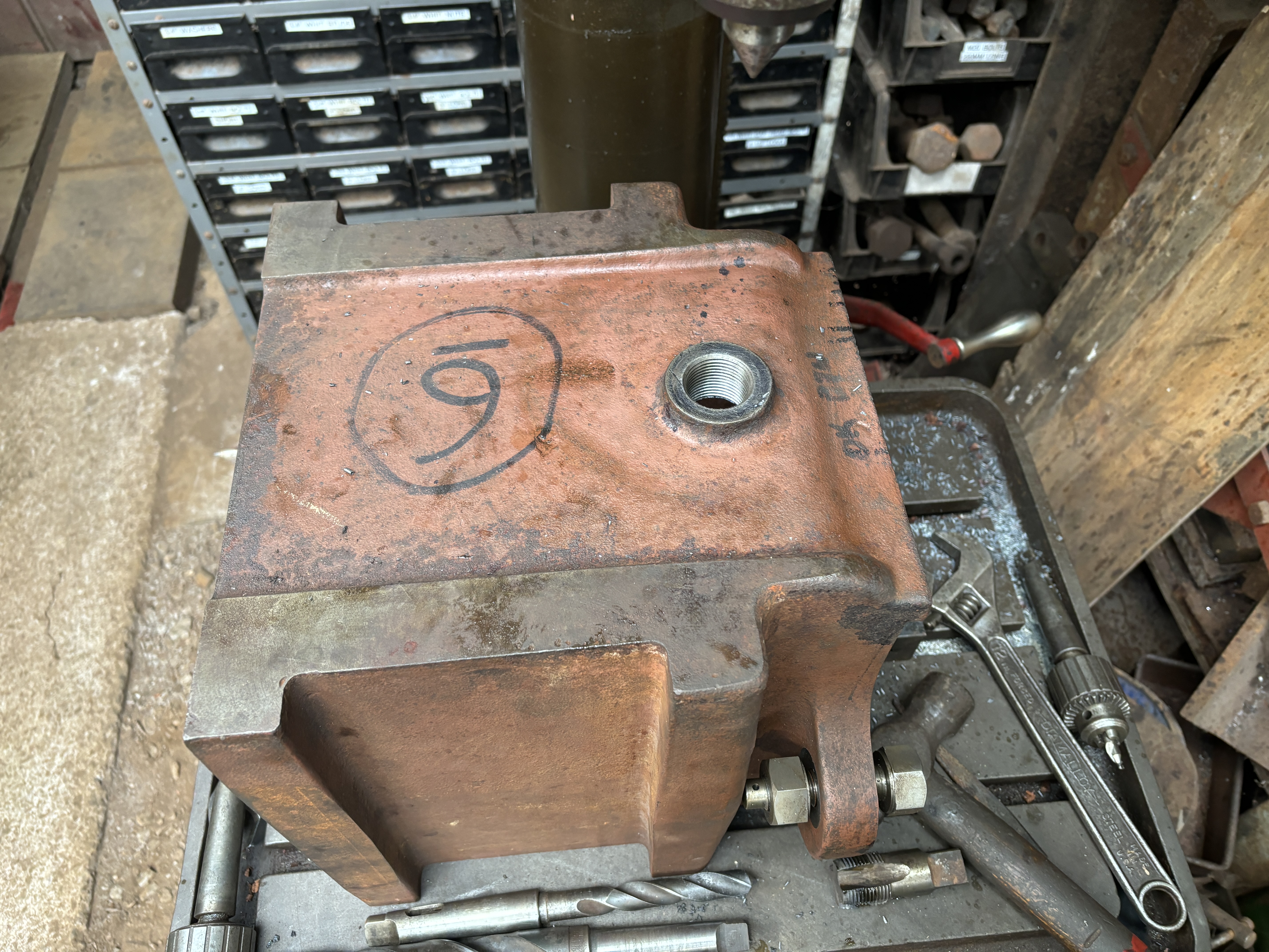
Although the tender chassis is relatively simple, there are lots of little detail bits that need attending to before it can be considered ‘done’. Here’s an example of one such item – a brake pin retaining clip which is held in place by two 5/8″ bolts which have their nuts split-pinned to prevent them from coming undone. The keen student of Whitworth bolting will note that these nuts are the slightly larger pre-war type.Another detailed point was the drilling and tapping of drain holes in the bottom of the new tender axlebox. These will allow the oil to be drained out rather than needing to be syphoned out.A cluster of newly made drain plugs for the axleboxes. The hole down the middle and radially thru’ the threads allows oil to drain out once the radial hole is exposed, but doesn’t require the plug to be fully removed. In this way the amount of oil release can be managed so that it’s not “all or nothing”.Drain plug trial fitted into its hole. Nice snug fit.Preliminary machining of the new tender axleboxes and their covers is now complete. The finish machining of the axleboxes will be done once the hornguides are setup on the chassis and we know the precise back to back and other dimensions that we need to work to.
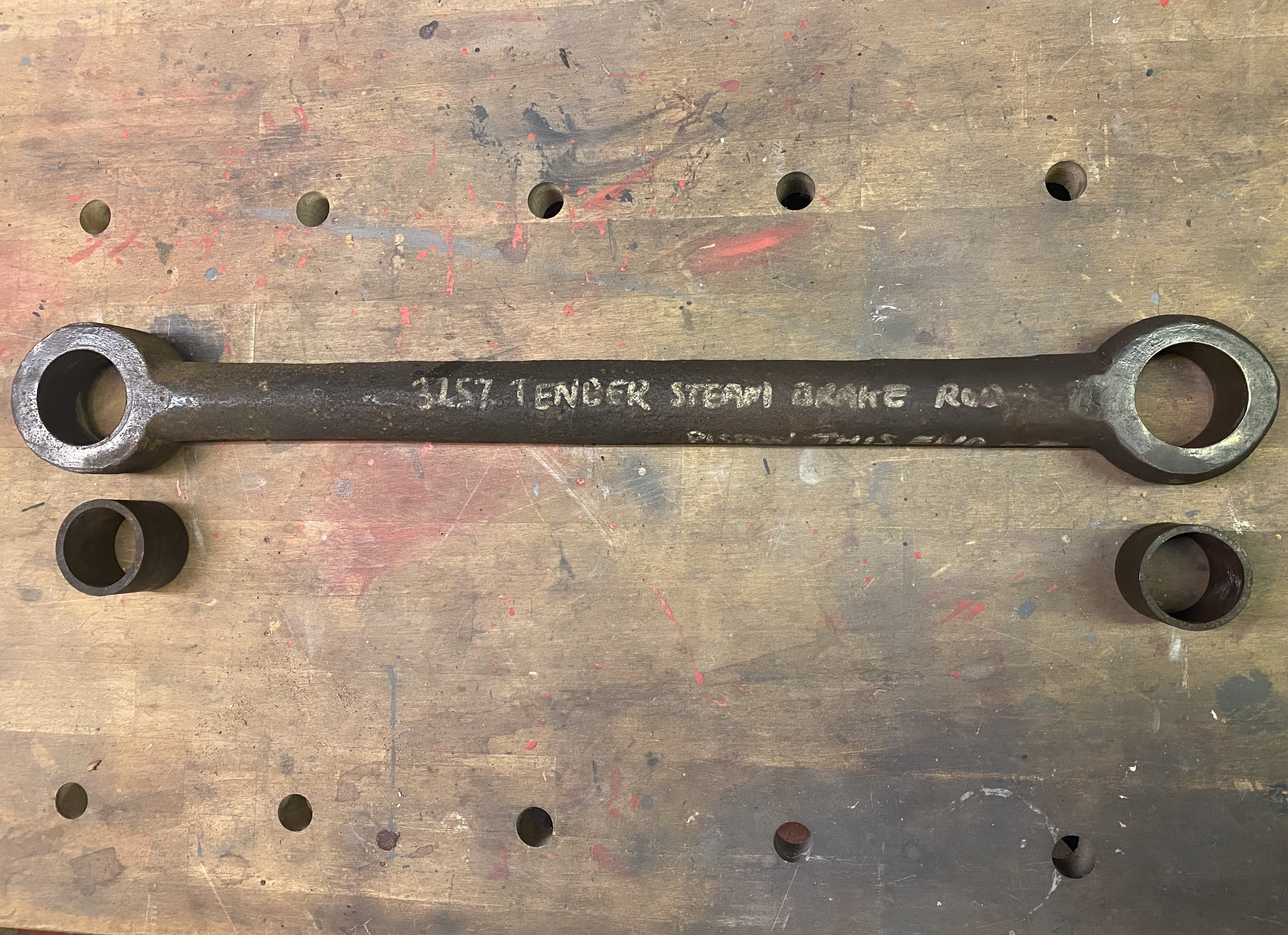
Work continues on the tender chassis and making it ready for re-wheeling. A lot of attention has been focussed on the steam brake system and in particular the manufacture of a new brake shaft to replace the unserviceable original.
The original tender brake shaft on the bench. The degree of pitting and general corrosion resulted in the decision to make a new one.
The orignal shaft was used to fabricate a special purpose jig to allow us to set the relative posiiton of the various arms in the correct locations when the refurbished arms are installed on the new shaft.
Jig for setting steam brake arms, with the original shaft in position.
The various arms which are attached to the shaft were cut-off, and each of them has now undergone an extensive amount of repair. This consists of building up the corroded areas with weld, restoring holes to the correct sizes, and re-bushing. This will ensure that everything is “in tolerance” and in as near to as new condition as we can get.
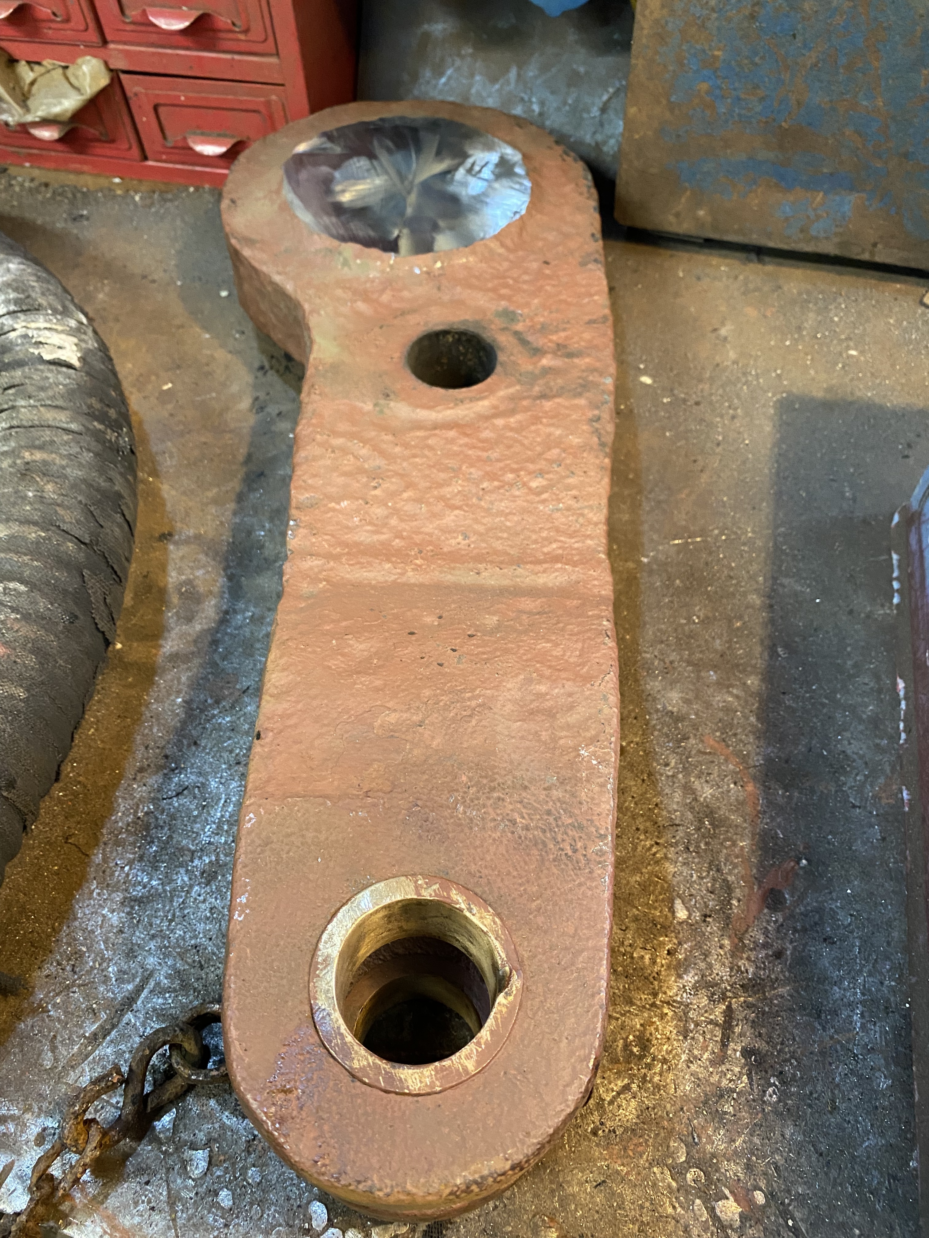
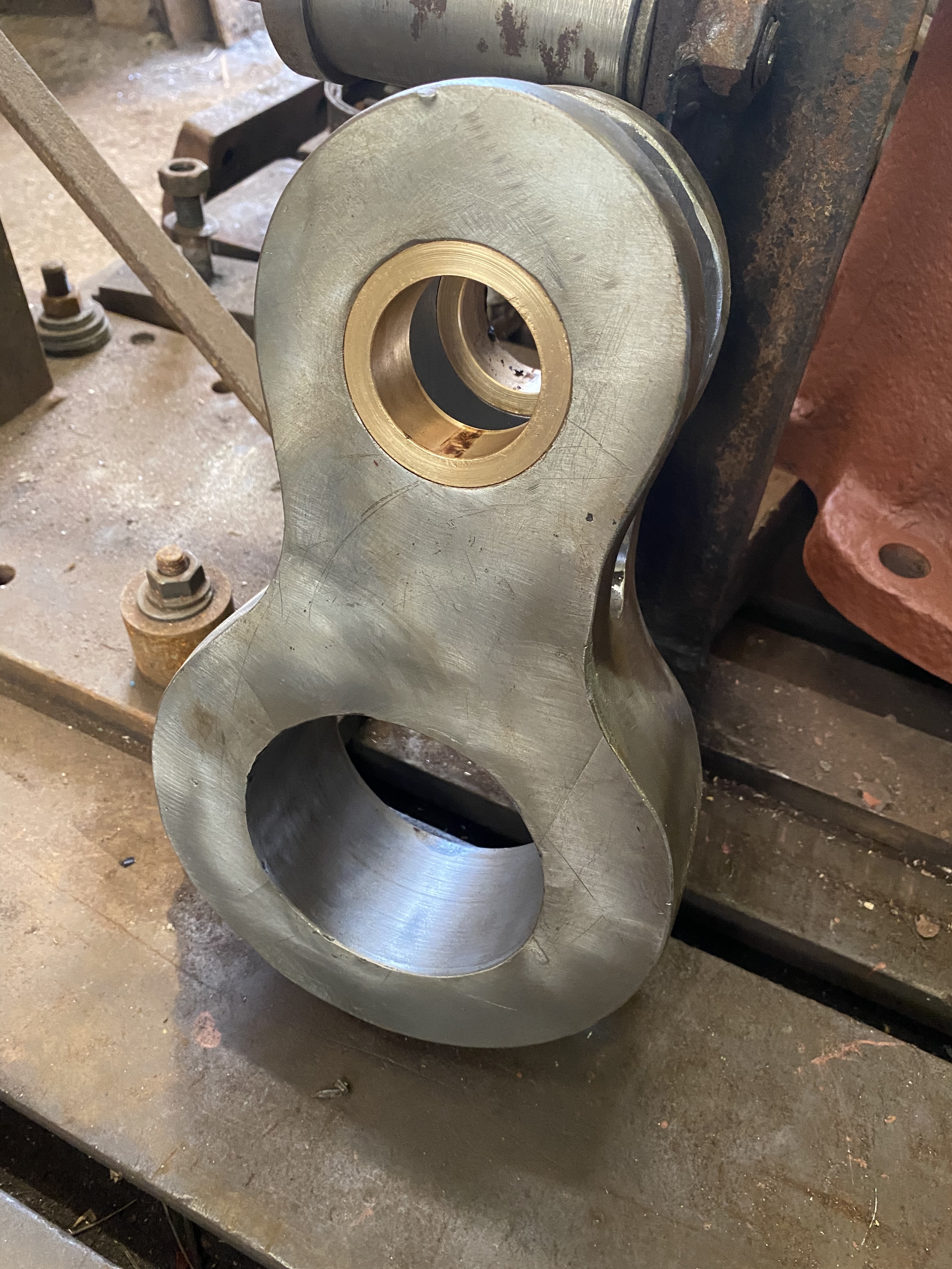
The original main steam brake arm after being cut off the shaft. Worn bushes and pitting from corrosion to be attended to.The arm during the process of weld-buildup to restore thickness to the metalArm during machining to correct dimensionsThe shaft end of the arm after machining One of the brake pull rod arms after machining and re-bushingBushes are made either from steel or gunmetal bronze as per the originals. Each bush has its own drawing showing the required dimensions and tolerances for the pin clearance and interference fit into the holeHere we see the tender steam brake piston rod before refurbishment with the original bushes removedAnd here it is after cleanup and with new bushes installed.
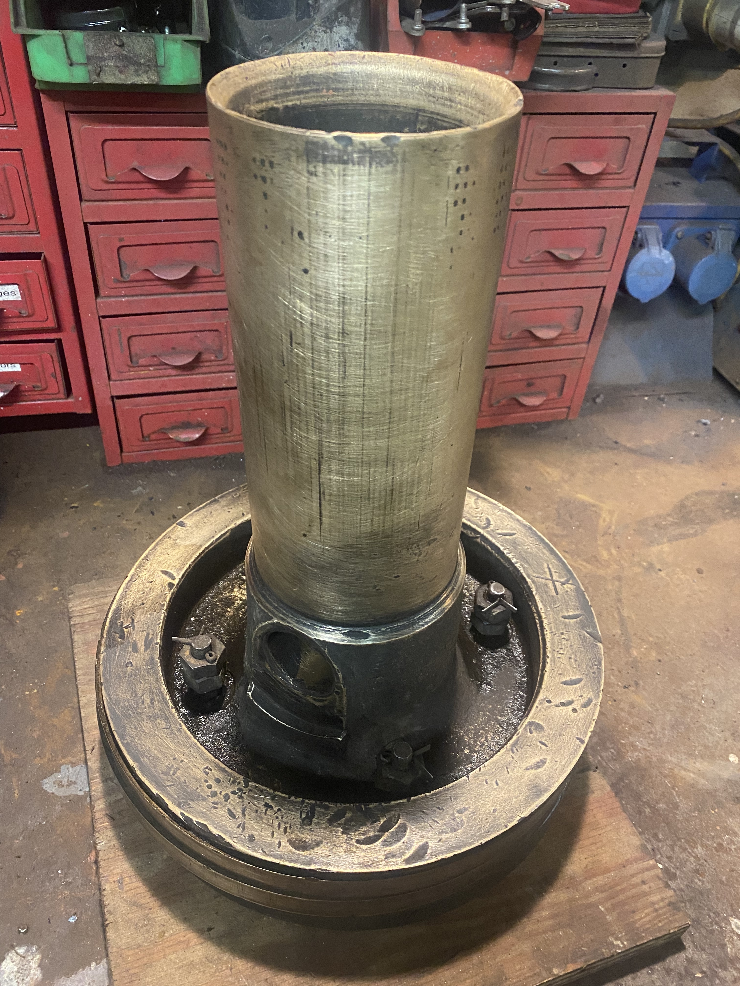
The original steam brake cylinder and piston have been retreived from storage, cleaned-up and dimensionally inspected. The restuls indicate that there is hardly any wear in eithe the cylinder or on the piston, which is is good news as it means that both can be re-used with only minor remedial work being required.
Tender steam brake piston after cleanupSteam brake cylinder after cleanup. The original machining marks from Crewe works may still be seen if one looks closely in the bore
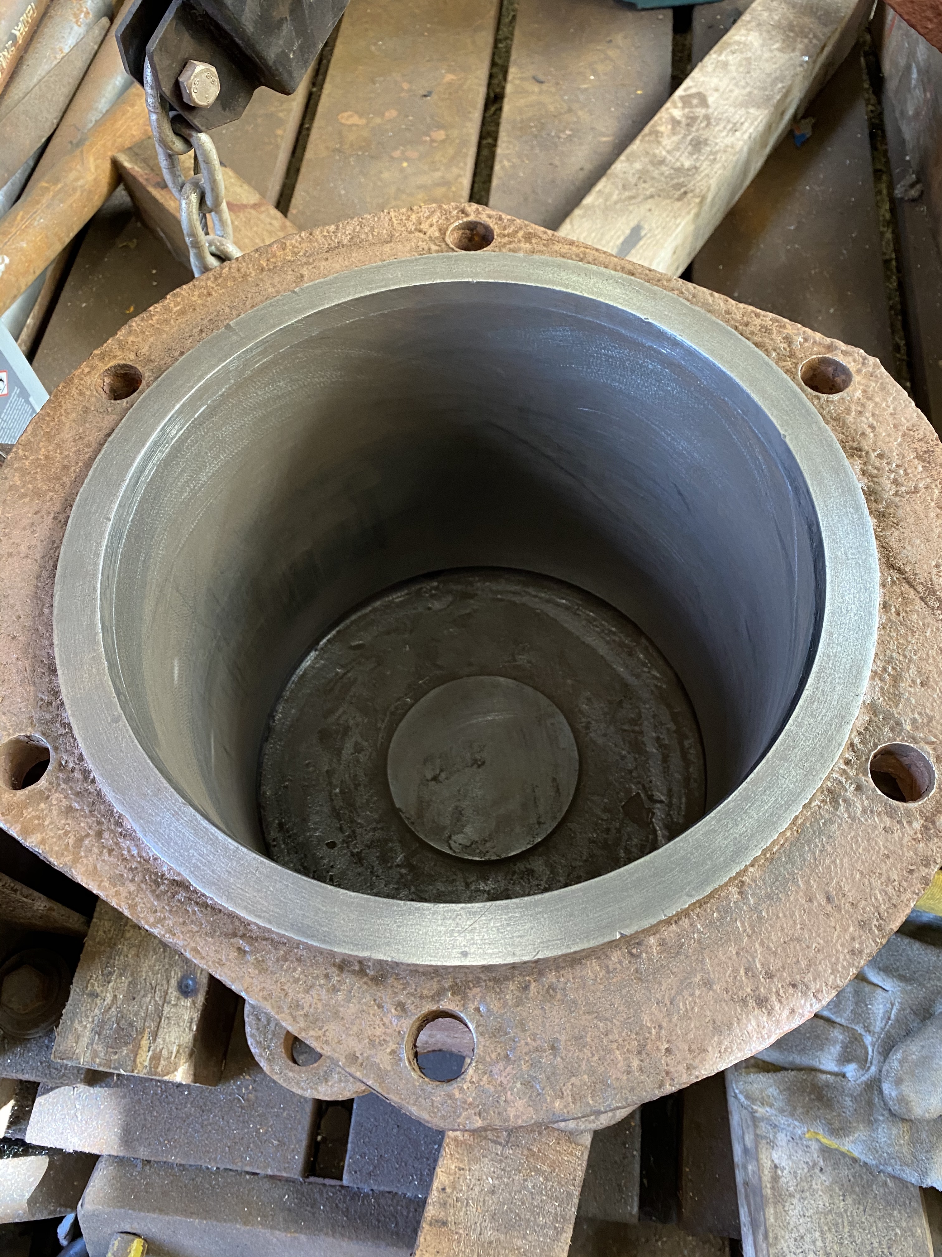
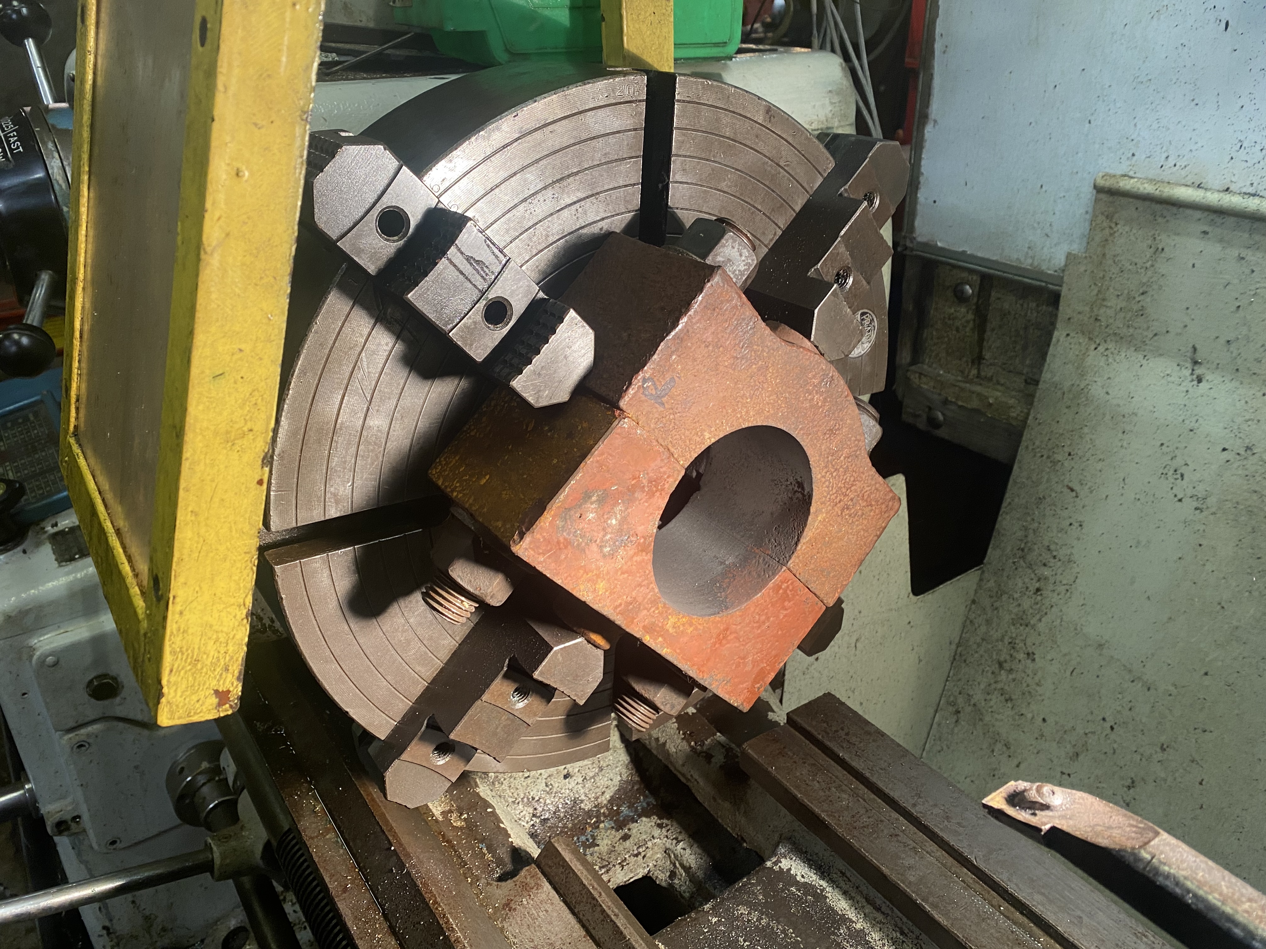
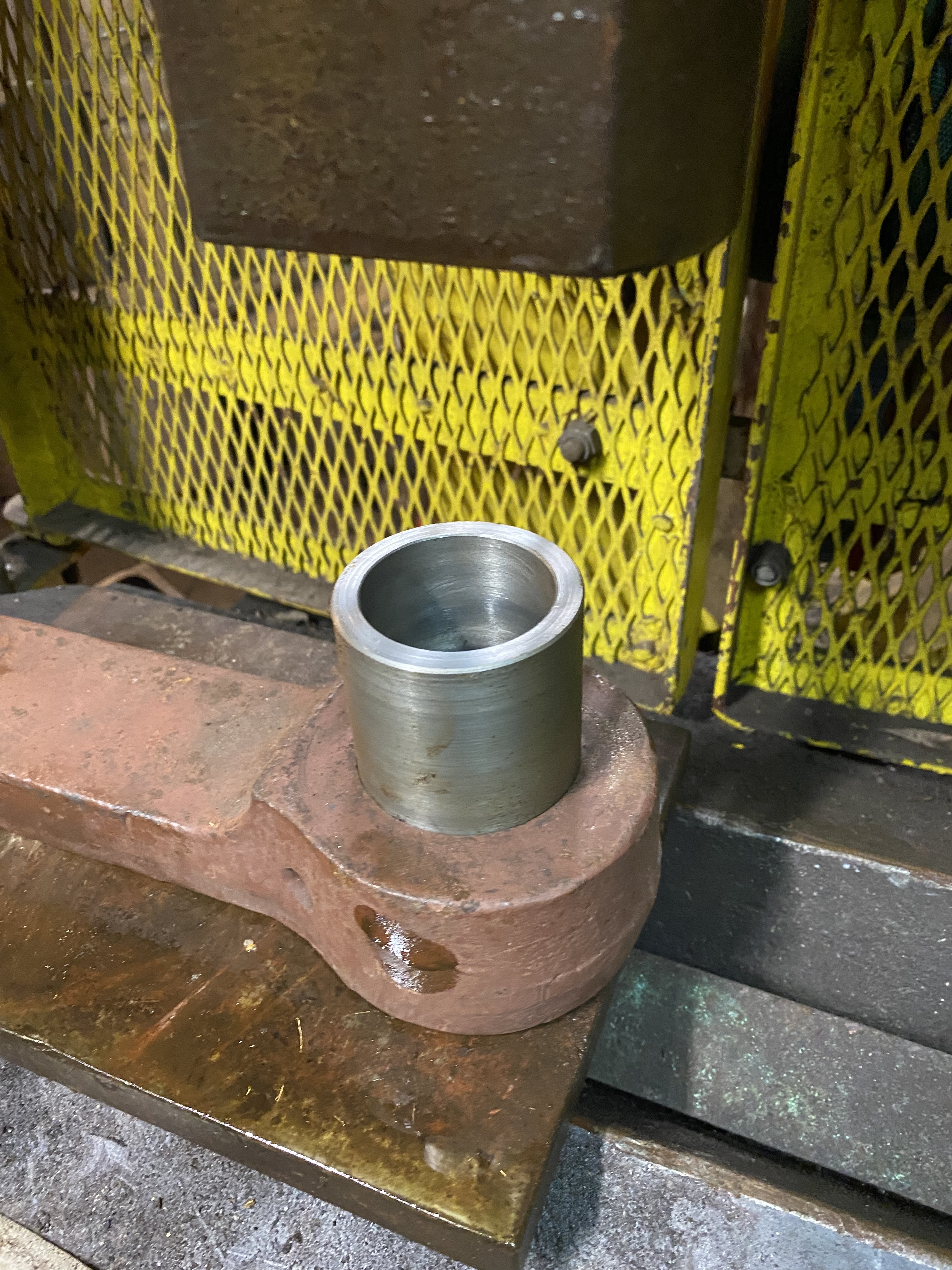
The original brake shaft intermediate bearing blocks have also been skim-machined to bring them back to true roundness, as they had worn a bit oval.
One of the brake shaft intermediate bearing blocks being machinedThe other block with the bore turned back into roundness
Other work on the tender chassis includes re-busing the spring hangar links and ongoing production of the numerous pins for the spring and brake gear. We have decided to make all pins and bushes from new so that all dimensions and tolerances are ‘as new’. None of this is particularly glamourous work, but it will result in the tender chassis being as high quality as we can make it, and we believe result in longevity and minimal maintenance in the long run.
Getting ready to press in a new bush to one of the tender spring hangar links. This is being done in our 100T hand-operated hydraulic pressPressing in part 1Pressing in part 2All the way in.
That’s about it for this update. Hopefully there will be some more new soon on the manufacture of the new tender brake shaft and setting up of the hornguides on the tender.