January 27th 2014.
We have just completed a very sucessful working weekend which saw progress on quite a few fronts. A brief summary is below.
Early on Saturday, we took delivery of the newly cast tender tank water vent pipes.
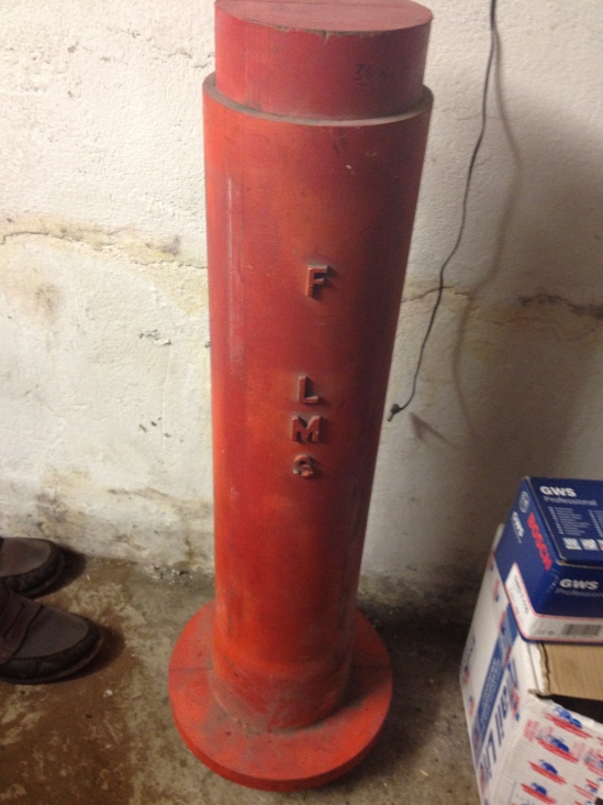
This is the wooden pattern which we made to allow us to cast the new tender tank vent pipes

And here are the finished castings.
Only two of these are needed for 4123 – one of them will be going to our friends at the Glouscester & Warwickshire Rly for sister 4F No. 4027
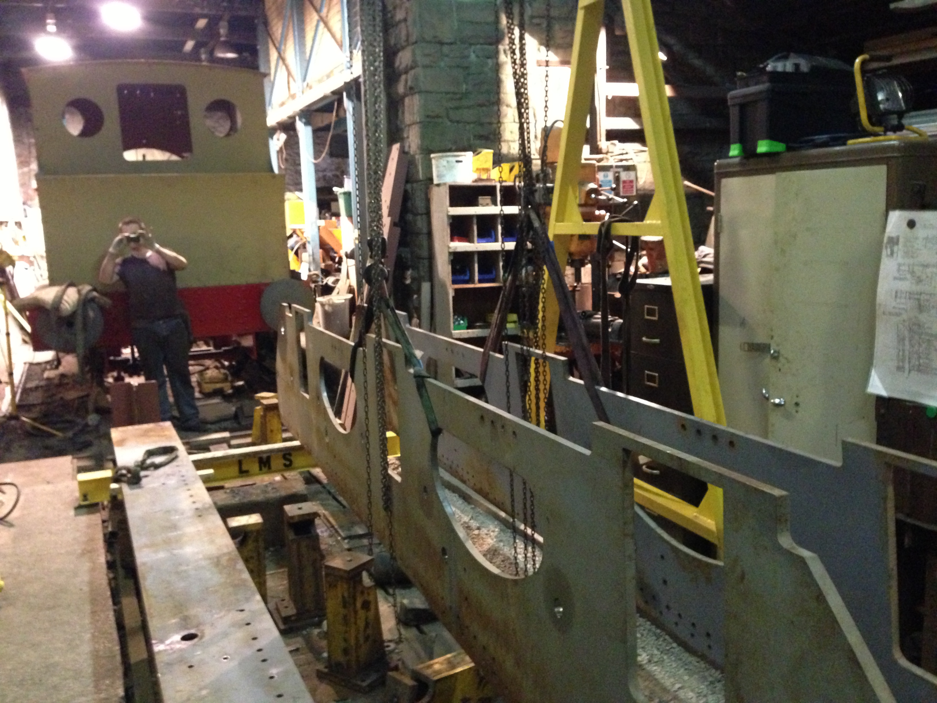
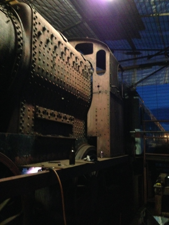
New(ish) volunteer George undertook the installation of the second inner frame for the tender, almost entirely on his own, and this is now ready for final setting up.
The second inner frame is shown installed (on the RHS of this picture).
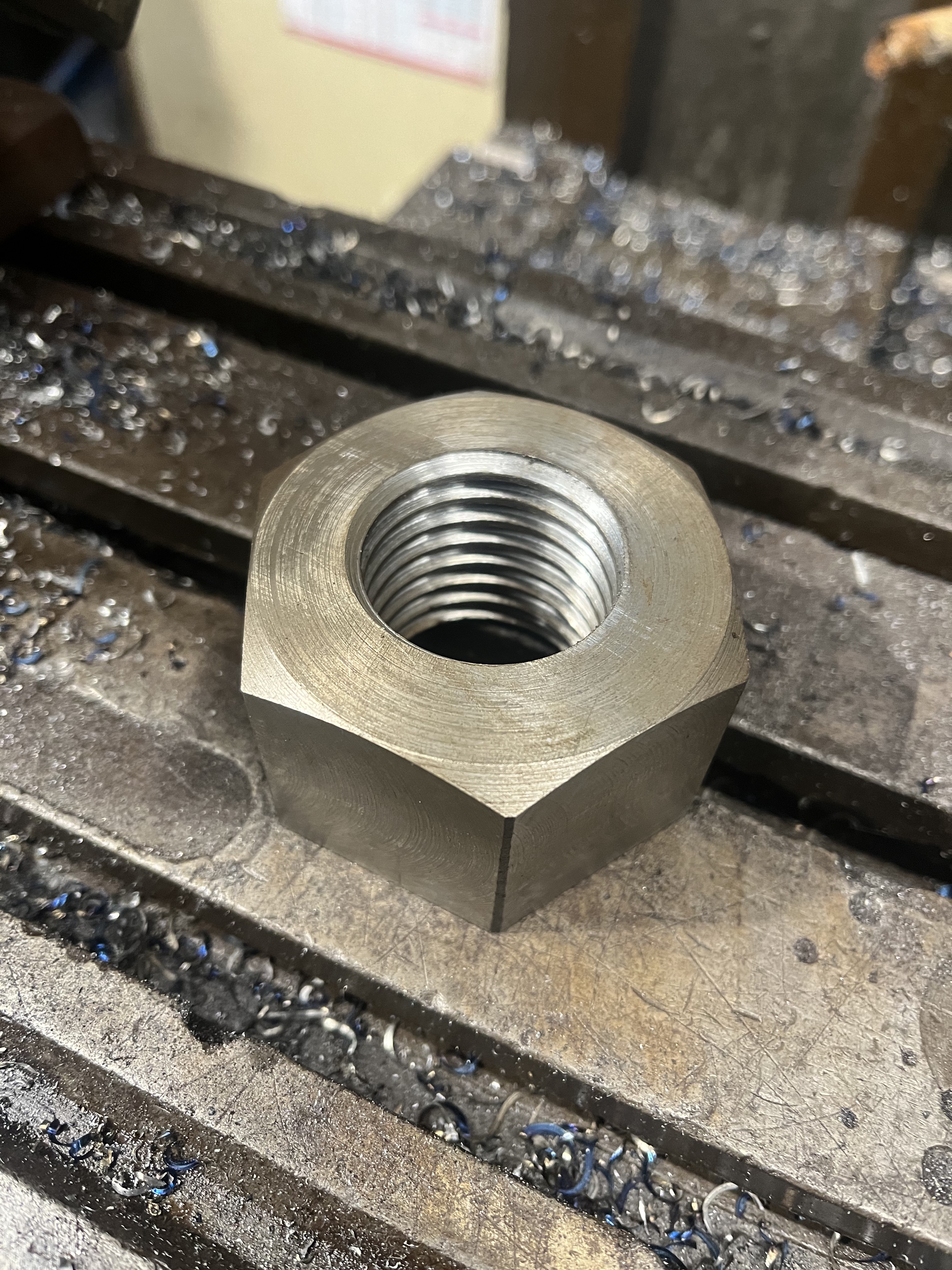
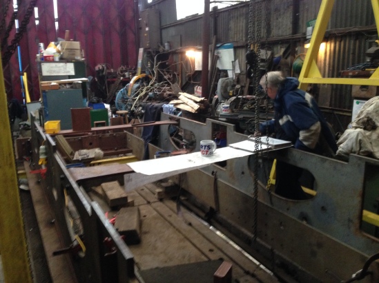
The first of the tender brake gear bushes have been made and fitted into the frames, which allows us to accurately line up the inner and outer frame plates before we start marking and drilling all the matching rivet holes.

The new gunmetal bushes which will hold the brake pins are shown after being press fitted into the frames.
The inner frame is nearest the camera with the outer frame behind.
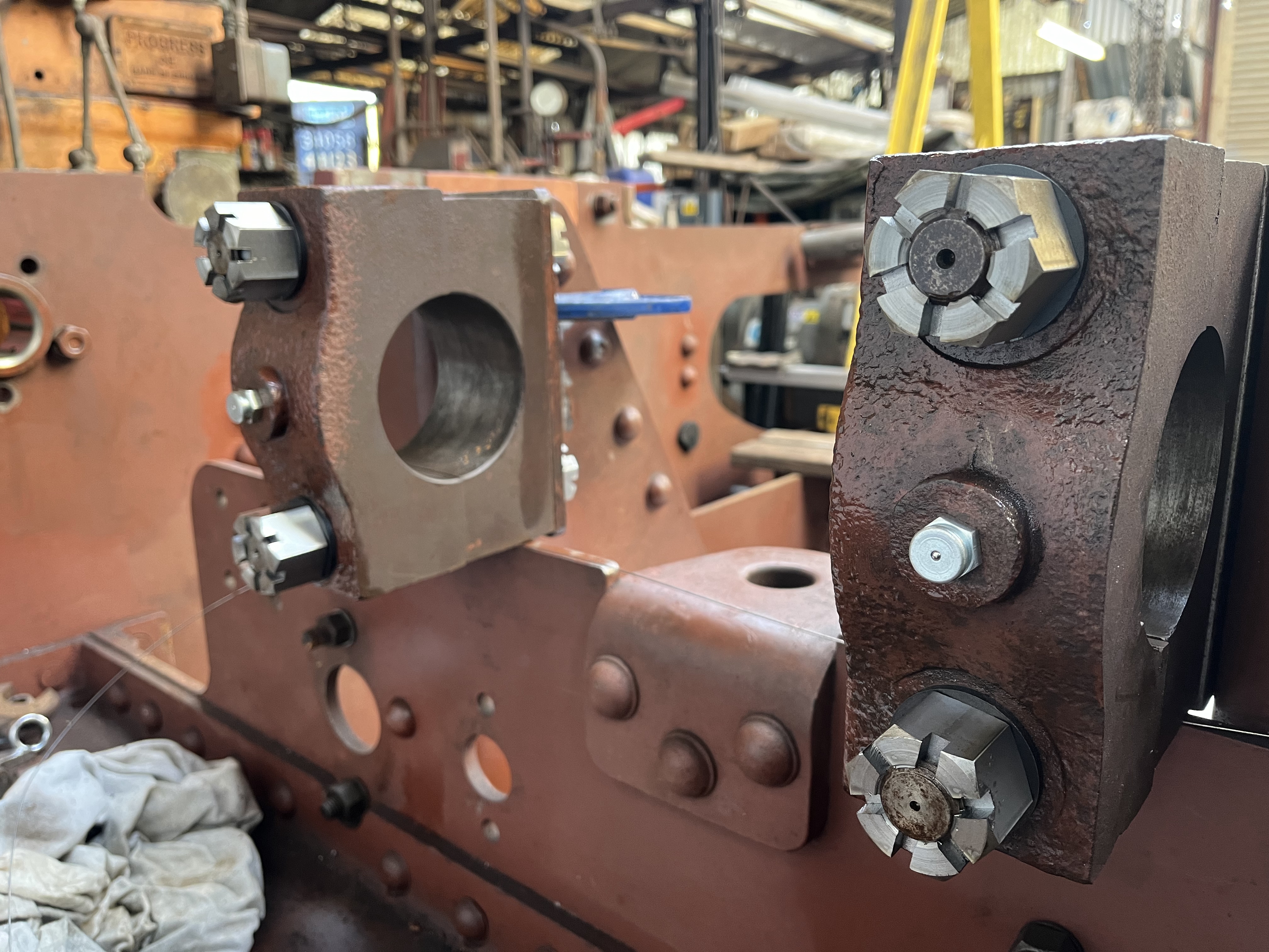
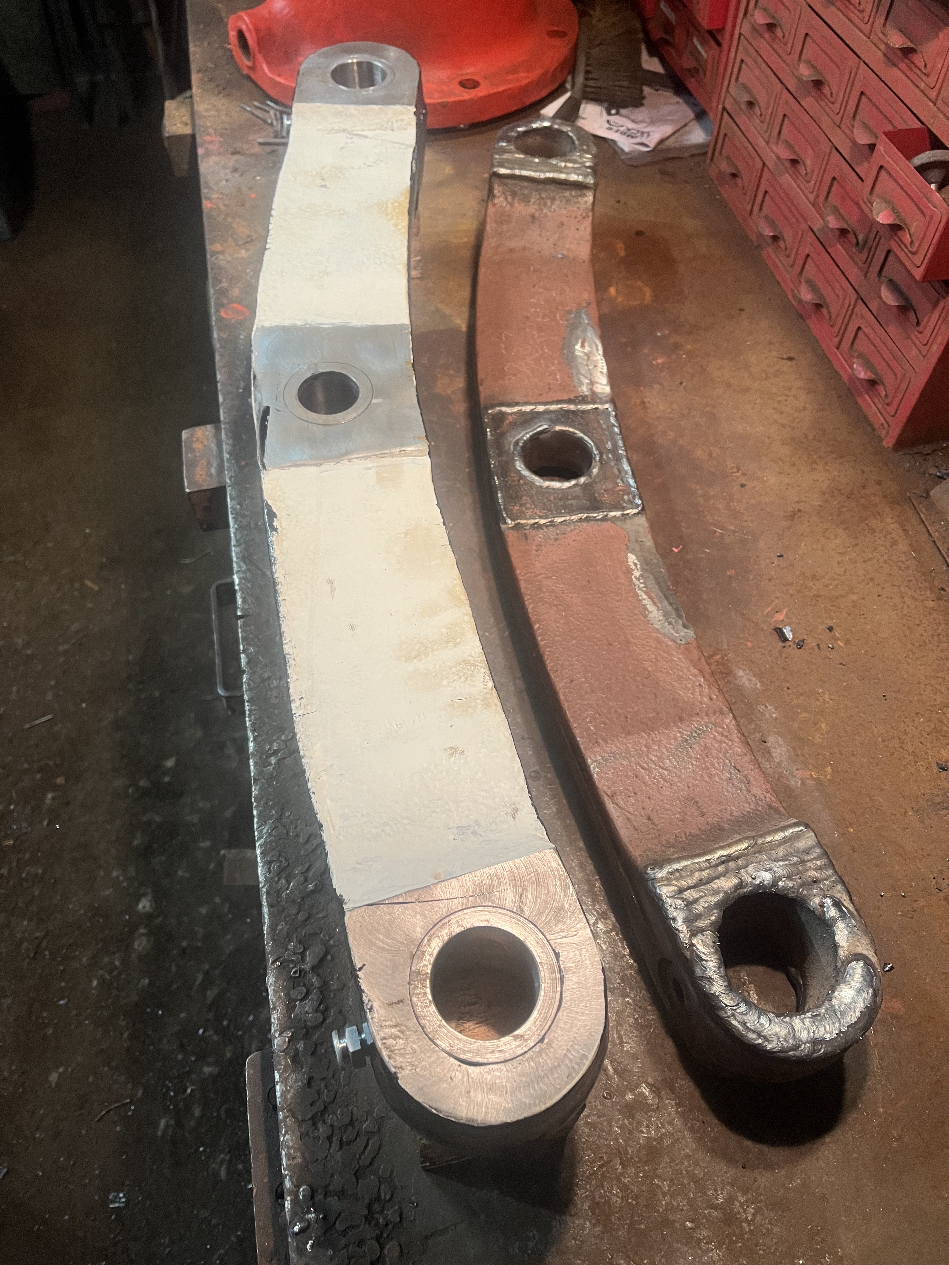
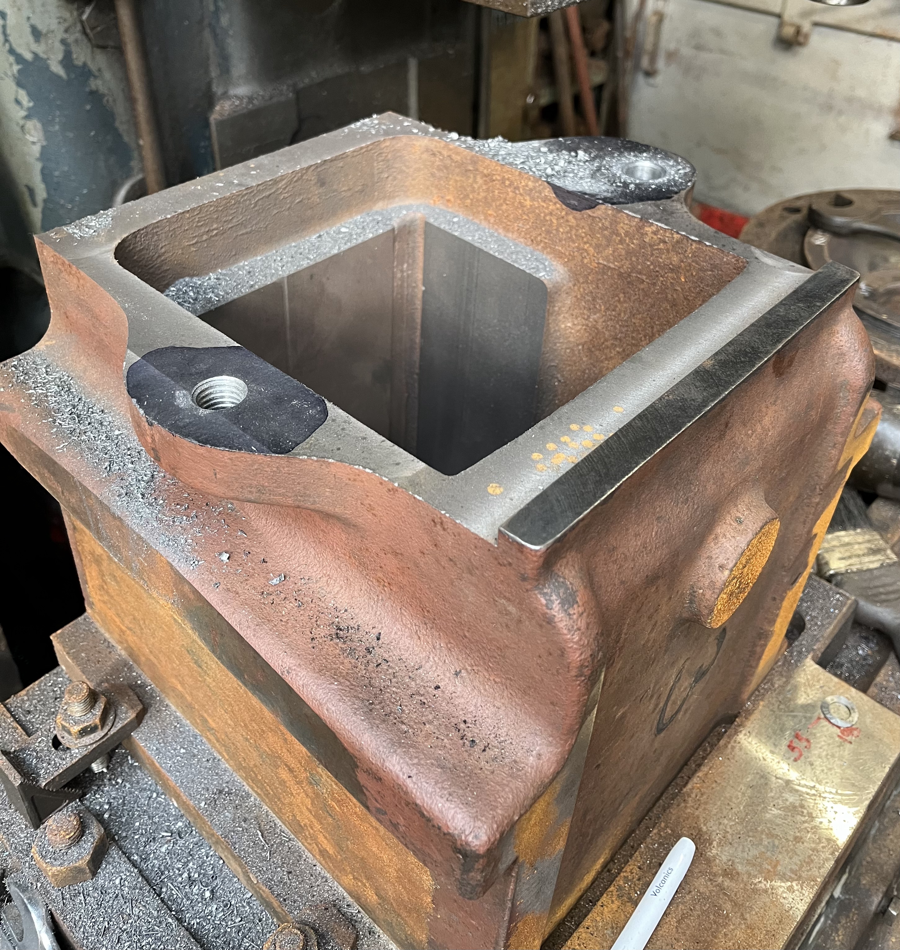
Over in the fabrication shop, fettling work contiuned on the new boiler support plate. This is a substantial lump of steel (it is 7/8″ thick) and requires a team effort to manipulate it into the various positions required for welding and grinding work.

The new boiler support plate is seen here having the various welds dressed prior to being released for final machining
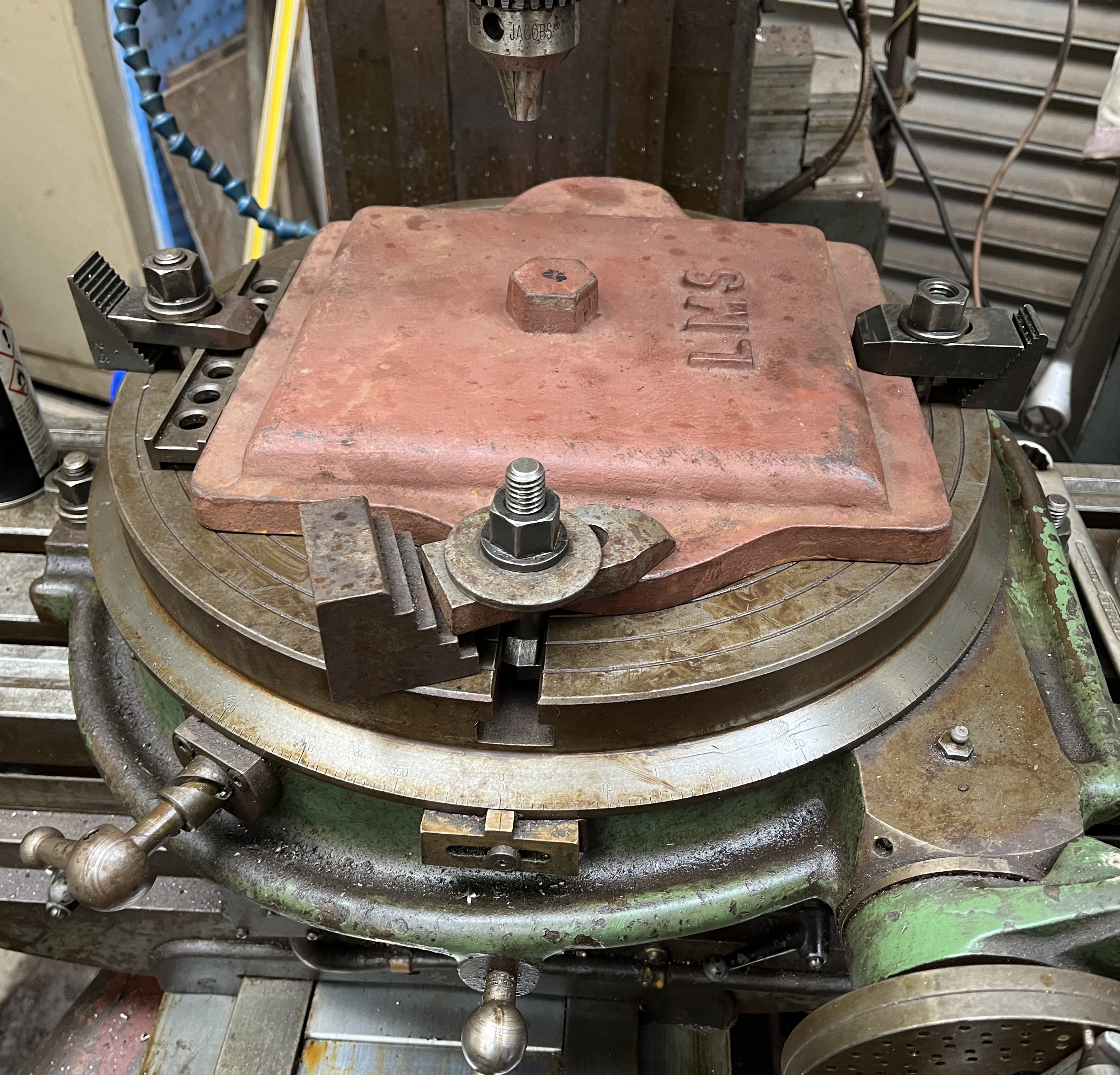
In addition, we made some further progress on the stripping of the loco – the first three sandboxes have been removed for repainting, along with various other minor items of platework and superstructure. We were pleased to welcome another new volunteer to our team – Rudy – who made a valuable contribution to many things, including coutersinking numerous rivet holes in the tender frames.
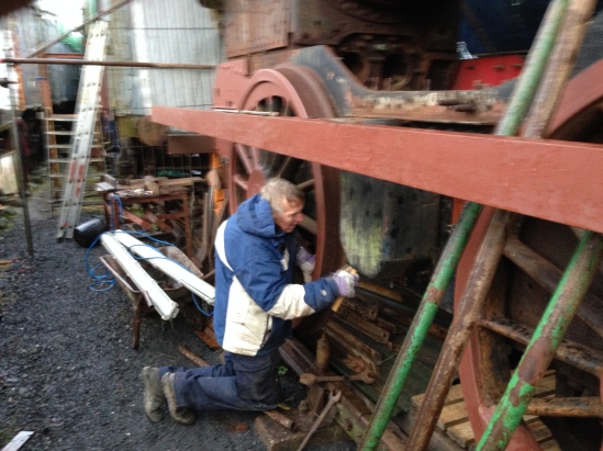
New Vounteer Rudy gets to grips with removing the middle sandbox
The dismanlting and cleaning of the cab steelwork is next. We had a ‘medium’ tidy up in our main stores van to give us a bit more room to store all the items which are being taken off the loco…. The van is almost full up, but not quite…!
And finally…. we made some improvements to the temporary shelter which 4123 is currently sitting in, including providing decent crawling boards in the ‘four-foot’ under the loco, and strip lighting in the ceiling. At least we can now (almost) see what we’re doing in these long and cold winter evenings…
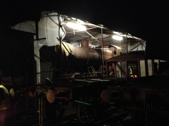
4123 sits patiently inside the temporary shelter was have built to keep the worst of the elements out
With a few more lights, we may actually be able to see what we’re working on…
The refurb of our tender wheelsets was compelted last year, and they spent a little bit of time on one of the AVR’s flat wagons, and indeed did quite a few miles and provided a nice sight being towed up and down during the AVR’s Autumn gala in 2013. However, they have now come back to earth and are back on the rails awaiting the day when we roll them under the new chassis. Hopefully that won’t be too far in the future now…
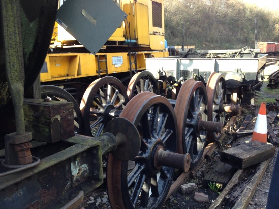
Tender wheels ready to go
That’s all for now. More soon we hope.